On this page
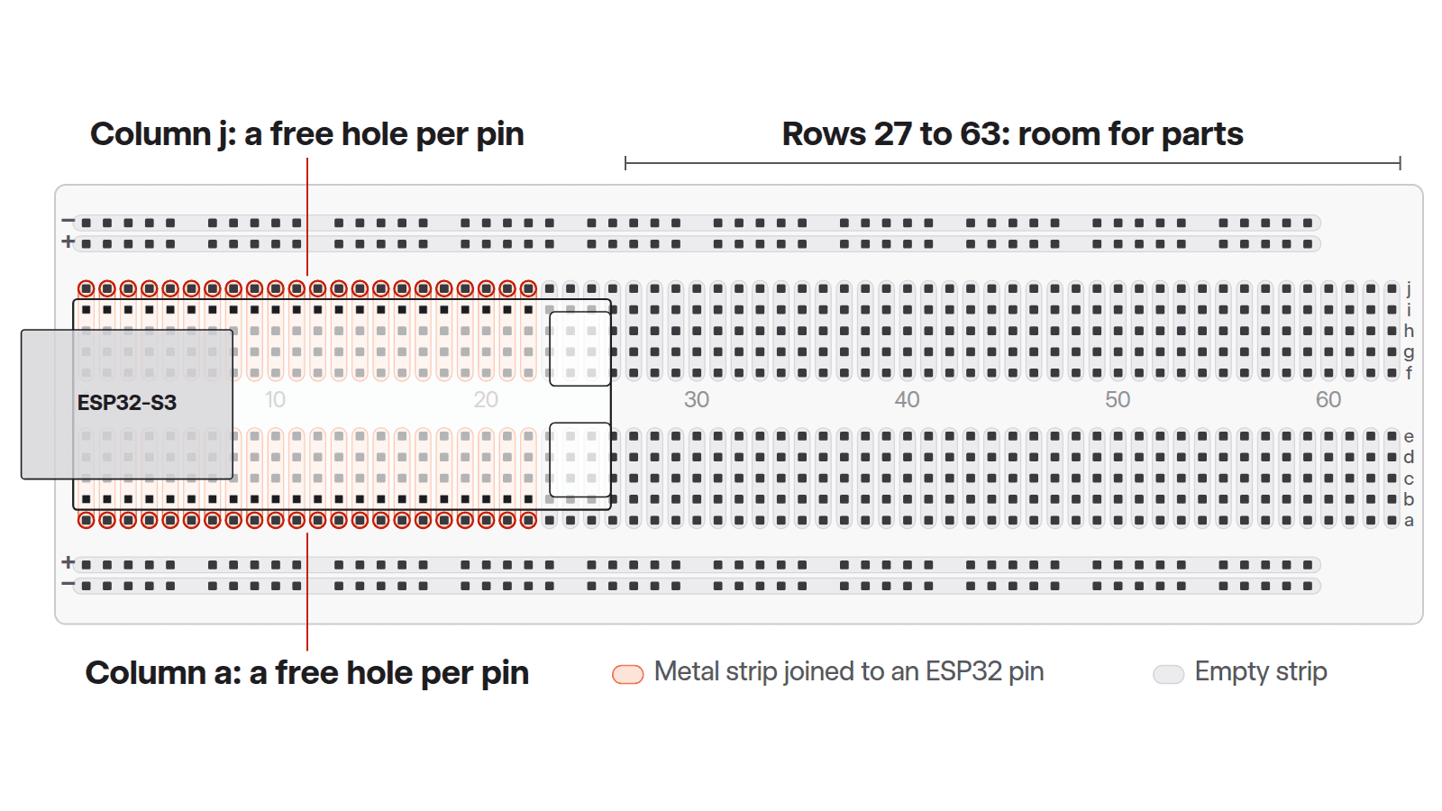
Push an ESP32-S3-DevKitC-1 into an 830-point breadboard so it straddles the center gap, and every one of its 44 pins gets a hole of its own with one free hole beside it. That free hole is where your first jumper wire goes.
The picture above is the whole trick. The orange bands are the metal strips hidden under the plastic. Each pin of the board sits on its own strip, so a wire pushed into the free hole at the end of that strip is connected to that pin.
How a breadboard works
A breadboard lets you connect parts without soldering. Under each group of holes is a springy metal clip, so anything pushed into the same group is connected, as if a short wire joined them underneath.
The 830-point breadboard in the Schematik Starter Kit has two kinds of groups:
| Area | What's connected | Count |
|---|---|---|
| Main area, left of the gap | Holes a to e in one numbered row | 63 strips of 5 |
| Main area, right of the gap | Holes f to j in one numbered row | 63 strips of 5 |
| Power rails | A long line of holes along each edge, marked + or − | 4 rails of 50 |
That adds up to 630 holes in the main area and 200 in the rails. The center gap splits every row in two, so hole e5 and hole f5 aren't connected.
Where the ESP32 goes
Put the board across the center gap with the module end (the silver can with the antenna) at row 1 and the USB-C ports toward the middle of the breadboard. On the kit board, the two pin headers are 22.86 mm apart, which is 9 hole spacings. A strip on each side has 5 holes, so the board fills 4 of them and leaves 1.
| Left header in | Right header in | Free holes per pin |
|---|---|---|
| Column a | Column h | 0 on the left, 2 on the right |
| Column b | Column i | 1 on each side |
| Column c | Column j | 2 on the left, 0 on the right |
Columns b and i are the only spot that leaves a free hole on both sides. In the pictures, the first 3V3 pin (the board's 3.3V power output) sits in hole b1 and the GND pin across from it in hole i1. Every hole number below assumes that layout.
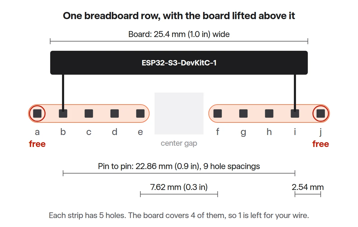
The board itself is 25.4 mm wide, so it covers the holes between its pins. That's why you can't plug anything into c to h next to a pin. The free hole in column a or j is the only way in.
The kit board arrives with its pin headers already soldered on. Line up both rows of pins over their holes, then press down on the edges of the board, not on the module, until the black plastic of the headers sits flat on the breadboard.
The board covers rows 1 to 26. Everything from row 27 onward is open for LEDs, buttons and sensors.
Wire the power rails
Most parts need power and ground. The rails along the edge give every part a short path to both.
- Run a jumper wire from hole a1 (3V3) to the + rail on the column a side.
- Run a jumper from hole a22 (GND) to the − rail on the same side.
Now the + rail carries 3.3V and the − rail is GND (ground, the shared return path for current).
Some breadboards split each rail in the middle. If yours does, add a short jumper across the break, or keep your parts on one half.
Add an LED on GPIO15
GPIO15 (general-purpose pin 15) is the eighth pin of the header in column b, so its free hole is a8. This LED is the green "comfortable" light from the room monitor below.
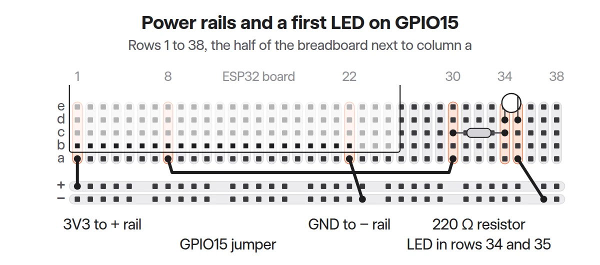
- Run a jumper from hole a8 (GPIO15) to hole a30.
- Put a 220 Ω resistor from c30 to c34. The resistor limits the current so the LED doesn't burn out.
- Put the LED's long leg (the anode, +) in d34 and its short leg (the cathode, −) in d35.
- Run a jumper from a35 to the − rail.
Each leg of a two-leg part sits in its own row. If both resistor legs sat in row 30, the resistor would connect row 30 to itself and do nothing.
Wire the room monitor
The room monitor from the kit's example projects shows temperature, humidity, light and motion on a small screen. Here's where each part connects, using the free holes from the layout above.
| Part | Part pin | ESP32 pin | Breadboard hole |
|---|---|---|---|
| 0.96" OLED screen (SSD1306) | VCC / GND / SDA / SCL | 3V3 / GND / GPIO8 / GPIO9 | + rail / − rail / a12 / a15 |
| DHT11 temperature sensor | VCC / DATA / GND | 3V3 / GPIO4 / GND | + rail / a4 / − rail |
| PIR motion sensor (HC-SR501) | VCC / OUT / GND | 5V / GPIO5 / GND | a21 / a5 / − rail |
| Light sensor (LM393) | VCC / DO / GND | 3V3 / GPIO6 / GND | + rail / a6 / − rail |
| Pushbutton | one side / other side | GPIO7 / GND | a7 / − rail |
| Green LED | anode / cathode | GPIO15 via 220 Ω / GND | a8 / − rail |
| Yellow LED | anode / cathode | GPIO16 via 220 Ω / GND | a9 / − rail |
| Red LED | anode / cathode | GPIO17 via 220 Ω / GND | a10 / − rail |
SDA carries data between the board and the screen, and SCL is the clock that keeps them in step. The PIR is the one part that runs on 5V, so give it its own wire from a21. Do not connect 5V to the + rail. That rail is joined to the 3V3 pin, and 5V there can damage the ESP32. The PIR's OUT pin sends 3.3V back, which is safe for the ESP32.
Use the light sensor's DO pin, not AO. DO switches between dark and light, and the blue knob on the module sets where it flips.
Check before you plug in USB
- Both headers sit in columns b and i, with the 3V3 pin in row 1.
- 3V3 goes to the + rail and GND goes to the − rail, not the other way around.
- 5V only goes to the PIR.
- Every part with two legs has them in two different rows.
- Every jumper wire lands in the row you meant. Count from the row numbers printed on the breadboard.
Unplug USB before you move a wire. The screen is only detected when the board starts, so if you fix its wiring, unplug USB and plug it back in.
Common mistakes
The board along a strip. Turned sideways, five pins of one header land in the same 5-hole strip and get connected to each other. Each header runs alongside the center gap, one on each side, so the board bridges the gap.
A wire one row off. Hole a13 is GPIO3, right next to GPIO8 in a12. Read the row number printed next to the hole, or count from row 1.
A rail that stops halfway. On a breadboard with split rails, parts on the far half get no power until you bridge the break.
The board in the rails. The rails connect a whole line of holes, so a header pushed into a rail connects all of its pins together.
What to build next
With the board on the breadboard and the rails wired, you're ready for a whole build. The CO2 room monitor and the ESP32 weather station are step-by-step projects you can open in Schematik. For a refresher on pin labels and pre-power checks, the beginner ESP32 hardware guide covers both. Which free hole would you use for a buzzer?
Keep building from here
Jump into a step-by-step build, or open Schematik and turn your own idea into code, wiring, and assembly instructions.
Related posts
New to Hardware? A Beginner ESP32 Guide for Your First Build
A beginner ESP32 hardware guide: what to buy first, how breadboards work, what pin labels mean, and what to check before powering your first build.
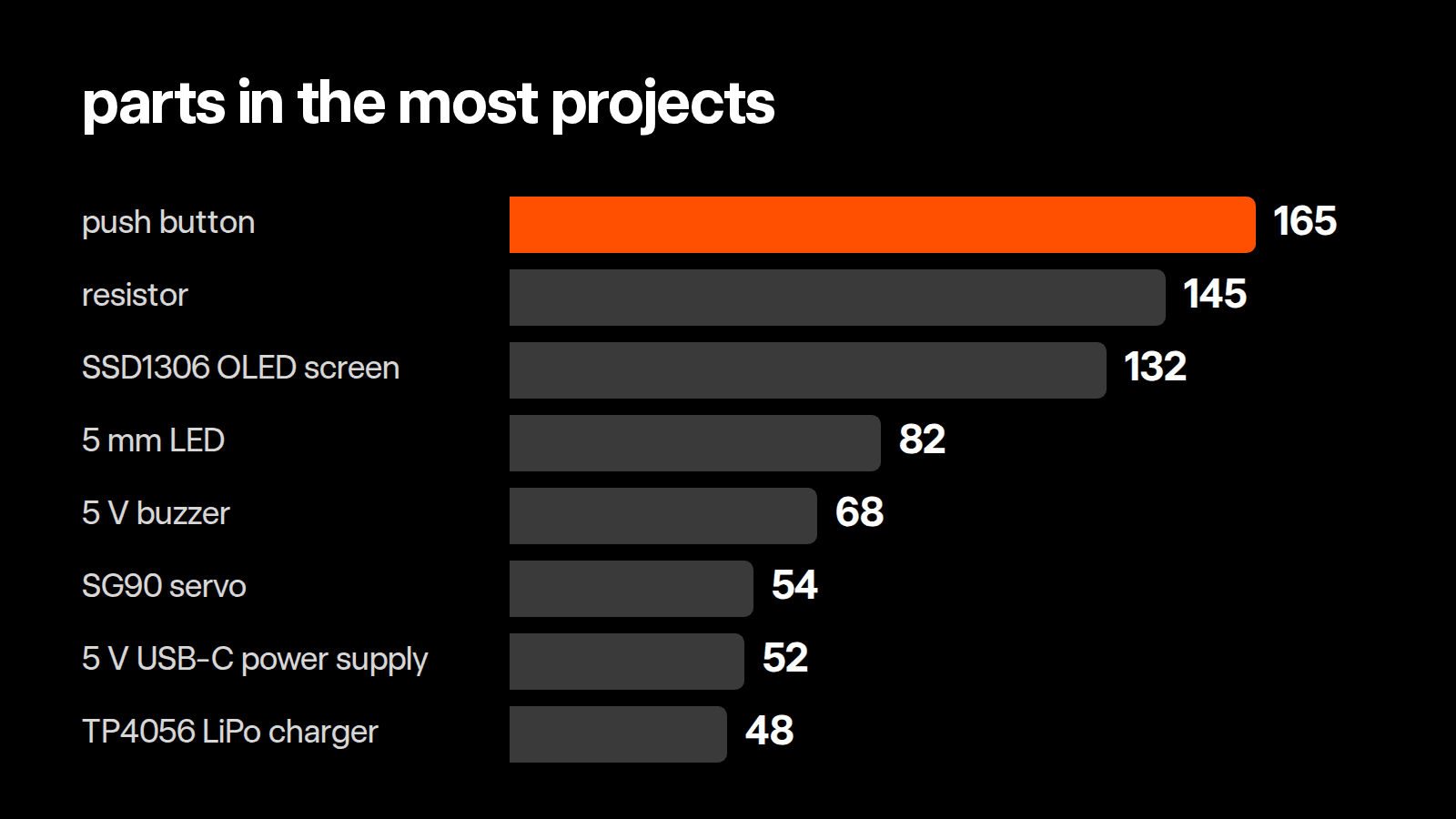
Most-used parts in Schematik projects
We counted the parts in all 902 published Schematik projects. A push button beat every screen and sensor, and one project in six adds no parts at all.
Related builds
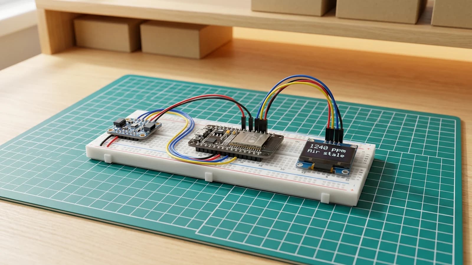
How to Build a CO2 Room Monitor with ESP32
Build an ESP32 CO2 monitor with an Adafruit SCD41 sensor, SSD1306 OLED, shared I2C wiring, warning thresholds, and live temperature and humidity readings.

How to Build a Tiny OLED Desk Command Centre
Build an ESP32 OLED desk display with Wi-Fi, weather, time, local IP printing, and a browser page for sending messages to the screen.

How to Build an ESP32 Weather Station with Clothing Advice
Build an ESP32 weather station that fetches Amsterdam forecast data over Wi-Fi and shows simple clothing advice on a Waveshare 1.83-inch LCD. Includes complete code and wiring guide.