On this page
Use 220Ω. On a 3.3V ESP32 pin it lets about 4 to 7mA (milliamps, thousandths of an amp) through a red or yellow LED, well under the LED's 20mA limit. On a 5V supply, 220Ω suits red, yellow and green. Green on a 3.3V pin is the exception, covered below.
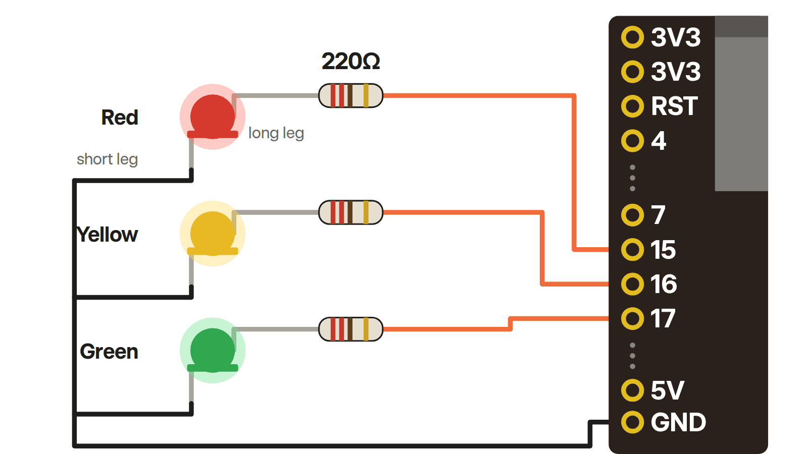
The diagram above shows the red, yellow and green LEDs from the Schematik Starter Kit, each with its own 220Ω resistor, on pins 15, 16 and 17 of the kit ESP32-S3 board. The long leg of each LED goes toward the pin. The short leg goes to GND, the ground pin where the current flows back to the board.
Why an LED needs a resistor
An LED doesn't limit its own current. Once the voltage across it passes its forward voltage, the voltage it needs to light up, the current climbs fast. Without a resistor it rises until something gives, usually the LED or the pin driving it. The resistor sets the current.
The formula
Take the supply voltage, subtract the LED's forward voltage and divide by the resistance in ohms (Ω):
I = (V − Vf) ÷ R
I is the current, V the supply voltage, Vf the forward voltage and R the resistance.
For a red LED with a typical 2.1V forward voltage on a 3.3V pin through 220Ω, that's 1.2V ÷ 220Ω, about 5.5mA.
Run it the other way to find the floor. With the LED's 20mA maximum and its lowest forward voltage, the kit red LED on 3.3V gives (3.3V − 1.8V) ÷ 20mA = 75Ω. That's the absolute limit with no margin for resistor tolerance or a warm LED, so stay well above it. A 220Ω resistor leaves plenty of room.
Estimated current for each kit LED
The kit LEDs' datasheet gives forward voltages measured at 20mA: 1.8V to 2.4V for red and yellow, 2.8V to 3.4V for green. Plugging those into the formula gives the estimates below, from the highest forward voltage to the lowest.
| LED | 3.3V pin, 220Ω | 3.3V pin, 1kΩ | 5V supply, 220Ω |
|---|---|---|---|
| Red | 4.1 to 6.8mA | 0.9 to 1.5mA | 11.8 to 14.5mA |
| Yellow | 4.1 to 6.8mA | 0.9 to 1.5mA | 11.8 to 14.5mA |
| Green | 0 to 2.3mA | 0 to 0.5mA | 7.3 to 10mA |
Treat these as estimates. The datasheet measures forward voltage at 20mA, and at lower currents an LED needs a little less voltage, so the real current comes out somewhat higher. The ESP32's output also sags a little under load, which pulls it back down. Every estimate stays well under the LED's 20mA rating.
The 5V column is for a 5V board like an Arduino Uno, or an LED wired to the ESP32's 5V pin so it stays on. ESP32 pins only put out 3.3V.
The 1kΩ column is for a status light you want to be dim, like a power indicator next to your bed.
Green on 3.3V
The kit green LED needs 2.8V to 3.4V at full current, close to the 3.3V a pin puts out. With 220Ω in the way, the estimate drops to about 1 to 2mA or less.
Green LEDs give more light per milliamp, though. The datasheet rates the kit green at 1,500 to 3,500mcd (millicandela, a measure of brightness) at 20mA, against 300 to 700mcd for red. So a green LED at low current can still show up well. Wire it up and judge it by eye.
If it's too dim, connect 2 of the kit's 220Ω resistors in parallel: both between the same pin and the same LED leg, side by side. That makes 110Ω, which lets more current through. Use that only for the green LED.
Code: cycle the 3 LEDs
#include <Arduino.h>

const int LEDS[] = {15, 16, 17};

void setup() {
  for (int pin : LEDS) {
    pinMode(pin, OUTPUT);
  }
}

void loop() {
  for (int pin : LEDS) {
    digitalWrite(pin, HIGH);
    delay(1000);
    digitalWrite(pin, LOW);
  }
}
Each LED lights for 1 second in turn: red, yellow, green.
Build it in Schematik
Open Schematik and describe what you want. It picks the parts, wires them and writes the code. Try one of these with the kit:
- "A traffic light with the red, yellow and green LEDs and a button for pedestrians."
- "Fade the green LED in and out like it's breathing."
- "Light the red LED when the room gets too warm, using the DHT11 temperature and humidity sensor."
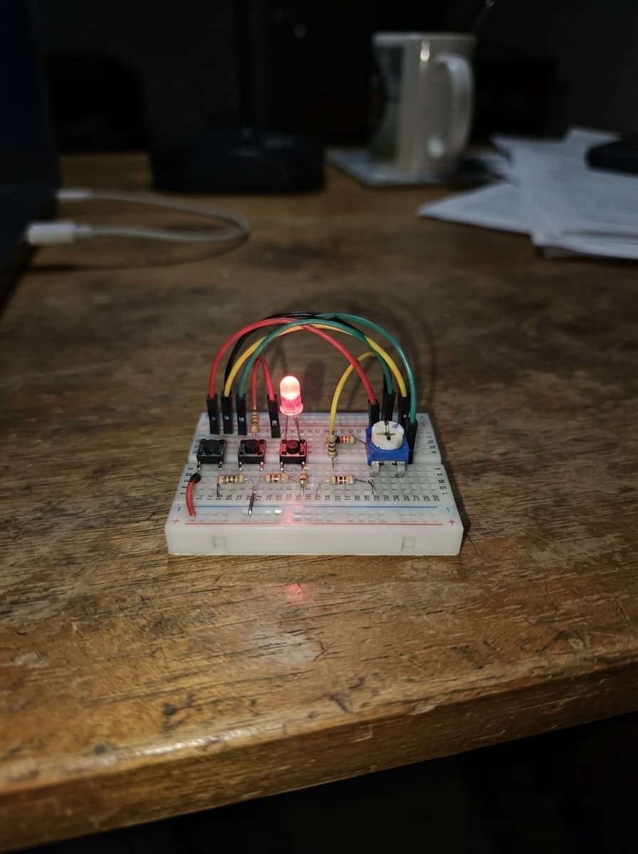
The three-button LED control project wires 3 LEDs with their resistors to an ESP32, with 3 push buttons to switch them.
FAQ
Can I use 330Ω instead of 220Ω? Yes. On 3.3V a red LED gets about 2.7 to 4.5mA, a little dimmer.
Does it matter which side of the LED the resistor goes on? No. The resistor works the same between the pin and the long leg or between the short leg and GND.
Do 2 LEDs in parallel need a resistor each? Yes. In parallel means both LEDs connect across the same 2 points. LEDs never match exactly, so with 1 shared resistor the LED with the lower forward voltage takes most of the current.
Keep building from here
Jump into a step-by-step build, or open Schematik and turn your own idea into code, wiring, and assembly instructions.
Related posts
New to Hardware? A Beginner ESP32 Guide for Your First Build
A beginner ESP32 hardware guide: what to buy first, how breadboards work, what pin labels mean, and what to check before powering your first build.
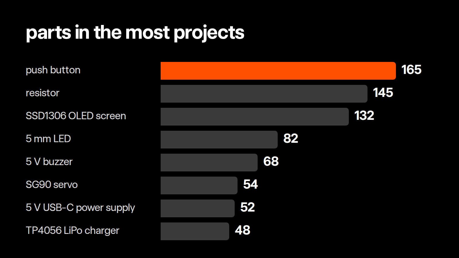
Most-used parts in Schematik projects
We counted the parts in all 902 published Schematik projects. A push button beat every screen and sensor, and one project in six adds no parts at all.