Community project
Three-Button LED Control
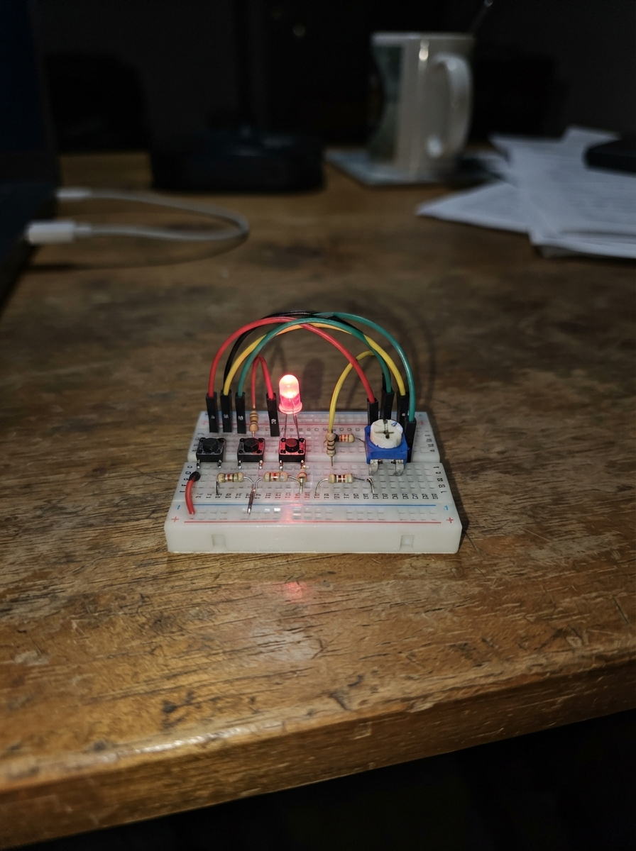
This project demonstrates how to control three LEDs independently using push buttons on an ESP32 microcontroller. Each button toggles its corresponding LED on and off, with brightness controlled by a potentiometer. The system also monitors temperature data from six MCP9808 sensors connected via I2C, reading values at regular intervals while managing button debouncing for reliable input detection.
The guide provides a complete wiring diagram showing how to connect the three push buttons, three LEDs with current-limiting resistors, the potentiometer for brightness adjustment, and all six temperature sensors to the ESP32. Assembly steps cover power rail setup, component connections, I2C address configuration, and firmware installation with debounce logic and PWM brightness control.
Wiring diagram

Gather all the parts
Assemble it in 7 steps
1. ทำรางไฟ 3.3 โวลต์และกราวด์
วาง ESP32-S3 ข้างเบรดบอร์ด แล้วต่อขา 3V3 ของบอร์ดเข้ารางบวกด้วยสายสีแดง และต่อขา GND เข้ารางลบด้วยสายสีดำ เพื่อให้ทุกชิ้นส่วนมีกราวด์ร่วมกัน.
- ใช้ราง 3V3 สำหรับเซ็นเซอร์ ตัวปรับ และสายสัญญาณ I2C ทั้งหมด
- อย่าต่อราง 3V3 เข้ากับขา 5V หรือ VIN เพราะไฟเกินอาจทำให้เซ็นเซอร์และขารับสัญญาณเสียหาย
2. ต่อปุ่มกด 3 ปุ่ม
เสียบปุ่มแต่ละตัวคร่อมร่องกลางของเบรดบอร์ด: button_1 ขาหนึ่ง → GPIO4 (สัญญาณ), อีกขา → GND (กราวด์); button_2 ขาหนึ่ง → GPIO5 (สัญญาณ), อีกขา → GND (กราวด์); button_3 ขาหนึ่ง → GPIO6 (สัญญาณ), อีกขา → GND (กราวด์).
- ขาปุ่มสองขาด้านเดียวกันมักเชื่อมกันอยู่แล้ว ให้เลือกต่อคนละด้านของปุ่ม
- ต้องวางปุ่มคร่อมร่องกลาง มิฉะนั้นปุ่มอาจต่อวงจรค้างและกดไม่ทำงาน
3. ต่อ LED พร้อมตัวต้านทาน
ต่อ resistor_1 ขาหนึ่ง → GPIO14 (สัญญาณ), อีกขา → ขายาวของ led_1; ขาสั้นของ led_1 → GND (กราวด์). ต่อ resistor_2 ขาหนึ่ง → GPIO15 (สัญญาณ), อีกขา → ขายาวของ led_2; ขาสั้นของ led_2 → GND (กราวด์). ต่อ resistor_3 ขาหนึ่ง → GPIO16 (สัญญาณ), อีกขา → ขายาวของ led_3; ขาสั้นของ led_3 → GND (กราวด์).
- ขายาวของ LED คือด้านบวก และตัวต้านทาน 220 Ω ใส่กลับด้านได้
- อย่าต่อ LED ตรงเข้าขา GPIO โดยไม่มีตัวต้านทาน 220 Ω เพราะกระแสสูงอาจทำให้ LED หรือบอร์ดเสียหาย
4. ต่อตัวปรับความสว่าง
ต่อขานอกด้านหนึ่งของ potentiometer_1 → 3V3 (ไฟเลี้ยง), ขากลาง → GPIO1 (สัญญาณปรับความสว่าง), และขานอกอีกด้าน → GND (กราวด์).
- หากหมุนแล้วสว่างเพิ่มในทิศที่ไม่ชอบ ให้สลับเฉพาะสายขานอกสองขา
- ห้ามใช้ 5V กับขานอกของตัวปรับ เพราะ GPIO1 รับแรงดันได้ไม่เกิน 3.3V
5. ตั้งที่อยู่ของเซ็นเซอร์ทั้ง 6 ตัว
ใช้ MCP9808 แบบที่มีจัมเปอร์เลือกที่อยู่ แล้วตั้งให้ไม่ซ้ำกัน: temperature_1 ใช้ 0x18 ไม่ต้องเชื่อมจัมเปอร์; temperature_2 เชื่อม A0 → 3V3 เพื่อใช้ 0x19; temperature_3 เชื่อม A1 → 3V3 เพื่อใช้ 0x1A; temperature_4 เชื่อม A1 และ A0 → 3V3 เพื่อใช้ 0x1B; temperature_5 เชื่อม A2 → 3V3 เพื่อใช้ 0x1C; temperature_6 เชื่อม A2 และ A0 → 3V3 เพื่อใช้ 0x1D.
- จัมเปอร์ A0/A1/A2 มักอยู่ด้านหลังโมดูลและอาจต้องบัดกรีหยดตะกั่วเพื่อเชื่อม
- การตั้งที่อยู่จะถูกอ่านตอนเปิดไฟ ดังนั้นให้ถอดและเสียบ USB ใหม่หลังเปลี่ยนจัมเปอร์
- หากเซ็นเซอร์สองตัวใช้ที่อยู่เดียวกัน บอร์ดจะอ่านค่าไม่ได้อย่างถูกต้อง
6. ต่อสายร่วมของเซ็นเซอร์อุณหภูมิ
ต่อเซ็นเซอร์ทุกตัวแบบขนานเข้ารางและสายชุดเดียวกัน: VCC ของ temperature_1 ถึง temperature_6 → 3V3 (ไฟเลี้ยง); GND ของ temperature_1 ถึง temperature_6 → GND (กราวด์); SDA ของ temperature_1 ถึง temperature_6 → GPIO8 (ข้อมูล); SCL ของ temperature_1 ถึง temperature_6 → GPIO9 (จังหวะสื่อสาร). ไม่ต้องต่อขา ALERT.
- ต่อ GPIO8 และ GPIO9 เป็นเส้นยาวสองเส้นบนเบรดบอร์ด แล้วแตกสายไปยังเซ็นเซอร์ทั้งหกตัว จะต่อได้เป็นระเบียบ
- โมดูล MCP9808 breakout ปกติมีตัวต้านทานช่วยดึงสายสัญญาณอยู่แล้ว
- VCC และ GND ที่สลับกันสามารถทำให้โมดูลเสียหายได้; ตรวจชื่อขาบนแผงของแต่ละตัวก่อนเสียบ USB
7. ตรวจสายและจ่ายไฟ
ตรวจว่า LED หันถูกด้าน ตรวจว่าจัมเปอร์ที่อยู่ของ MCP9808 ทั้ง 6 ตัวไม่ซ้ำกัน และทุกโมดูลต่อกับ 3V3 ไม่ใช่ 5V จากนั้นเสียบ USB เข้าบอร์ด.
- หลังแฟลช โปรแกรมจะแสดงค่าอุณหภูมิของแต่ละจุดทุก 1 วินาทีในหน้าต่างข้อความของบอร์ด
- หากบอร์ดหรือเซ็นเซอร์ร้อนผิดปกติ ให้ถอด USB ทันที แล้วตรวจสาย 3V3 และ GND ใหม่
Review all connections
1. Connections between "button_1" and "ESP32"
2. Connections between "button_2" and "ESP32"
3. Connections between "button_3" and "ESP32"
4. Connections between "potentiometer_1" and "ESP32"
5. Connections between "resistor_1" and "ESP32"
6. Connections between "led_1" and "ESP32"
7. Connections between "resistor_2" and "ESP32"
8. Connections between "led_2" and "ESP32"
9. Connections between "resistor_3" and "ESP32"
10. Connections between "led_3" and "ESP32"
11. Connections between "temperature_1" and "ESP32"
12. Connections between "temperature_2" and "ESP32"
13. Connections between "temperature_3" and "ESP32"
14. Connections between "temperature_4" and "ESP32"
15. Connections between "temperature_5" and "ESP32"
16. Connections between "temperature_6" and "ESP32"
Deploy the firmware
#include <Arduino.h>
#include <Wire.h>
#include <Adafruit_MCP9808.h>

const int BUTTON_1_PIN = 4;
const int BUTTON_2_PIN = 5;
const int BUTTON_3_PIN = 6;
const int POT_PIN = 1;
const int LED_1_PIN = 14;
const int LED_2_PIN = 15;
const int LED_3_PIN = 16;
const int I2C_SDA_PIN = 8;
const int I2C_SCL_PIN = 9;

const uint32_t PWM_FREQUENCY = 5000;
const uint8_t PWM_RESOLUTION = 8;
const uint32_t DEBOUNCE_MS = 35;
const uint32_t TEMPERATURE_INTERVAL_MS = 1000;
const uint8_t SENSOR_COUNT = 6;
const uint8_t SENSOR_ADDRESSES[SENSOR_COUNT] = {0x18, 0x19, 0x1A, 0x1B, 0x1C, 0x1D};

struct ButtonState {
  int pin;
  bool ledOn;
  int lastReading;
  int stableState;
  unsigned long lastChangeMs;
};

ButtonState buttons[] = {
  {BUTTON_1_PIN, false, HIGH, HIGH, 0},
  {BUTTON_2_PIN, false, HIGH, HIGH, 0},
  {BUTTON_3_PIN, false, HIGH, HIGH, 0}
};

const int ledPins[] = {LED_1_PIN, LED_2_PIN, LED_3_PIN};
Adafruit_MCP9808 temperatureSensors[SENSOR_COUNT];
bool sensorPresent[SENSOR_COUNT] = {false, false, false, false, false, false};
uint8_t brightness = 0;
unsigned long lastTemperatureReadMs = 0;

void updateLeds() {
  for (int i = 0; i < 3; i++) {
    ledcWrite(ledPins[i], buttons[i].ledOn ? brightness : 0);
  }
}

void readButtons() {
  unsigned long now = millis();

  for (int i = 0; i < 3; i++) {
    int reading = digitalRead(buttons[i].pin);

    if (reading != buttons[i].lastReading) {
      buttons[i].lastChangeMs = now;
      buttons[i].lastReading = reading;
    }

    if ((now - buttons[i].lastChangeMs) >= DEBOUNCE_MS && reading != buttons[i].stableState) {
      buttons[i].stableState = reading;
      if (buttons[i].stableState == LOW) {
        buttons[i].ledOn = !buttons[i].ledOn;
        updateLeds();
      }
    }
  }
}

void readBrightness() {
  int rawValue = analogRead(POT_PIN);
  uint8_t newBrightness = map(rawValue, 0, 4095, 0, 255);

  if (abs((int)newBrightness - (int)brightness) >= 2) {
    brightness = newBrightness;
    updateLeds();
  }
}

void startTemperatureSensors() {
  Serial.println("Starting MCP9808 temperature sensors");
  for (uint8_t i = 0; i < SENSOR_COUNT; i++) {
    sensorPresent[i] = temperatureSensors[i].begin(SENSOR_ADDRESSES[i], &Wire);
    Serial.printf("Sensor %u at 0x%02X: %s\n", i + 1, SENSOR_ADDRESSES[i],
                  sensorPresent[i] ? "found" : "not found");
  }
}

void readTemperatures() {
  unsigned long now = millis();
  if (now - lastTemperatureReadMs < TEMPERATURE_INTERVAL_MS) {
    return;
  }
  lastTemperatureReadMs = now;

  for (uint8_t i = 0; i < SENSOR_COUNT; i++) {
    if (!sensorPresent[i]) {
      continue;
    }
    float temperatureC = temperatureSensors[i].readTempC();
    Serial.printf("Temperature %u: %.2f C\n", i + 1, temperatureC);
  }
  Serial.println();
}

void setup() {
  Serial.begin(115200);
  analogReadResolution(12);

  for (int i = 0; i < 3; i++) {
    pinMode(buttons[i].pin, INPUT_PULLUP);
    ledcAttach(ledPins[i], PWM_FREQUENCY, PWM_RESOLUTION);
    ledcWrite(ledPins[i], 0);
  }

  Wire.begin(I2C_SDA_PIN, I2C_SCL_PIN);
  startTemperatureSensors();
}

void loop() {
  readButtons();
  readBrightness();
  readTemperatures();
}
Remix this project
Make it yours in one click
Open a full copy of this project in your own Schematik workspace — diagram, code, parts, and assembly steps included. Swap the sensor, add features, or redesign the whole thing with AI. The author's original stays untouched.