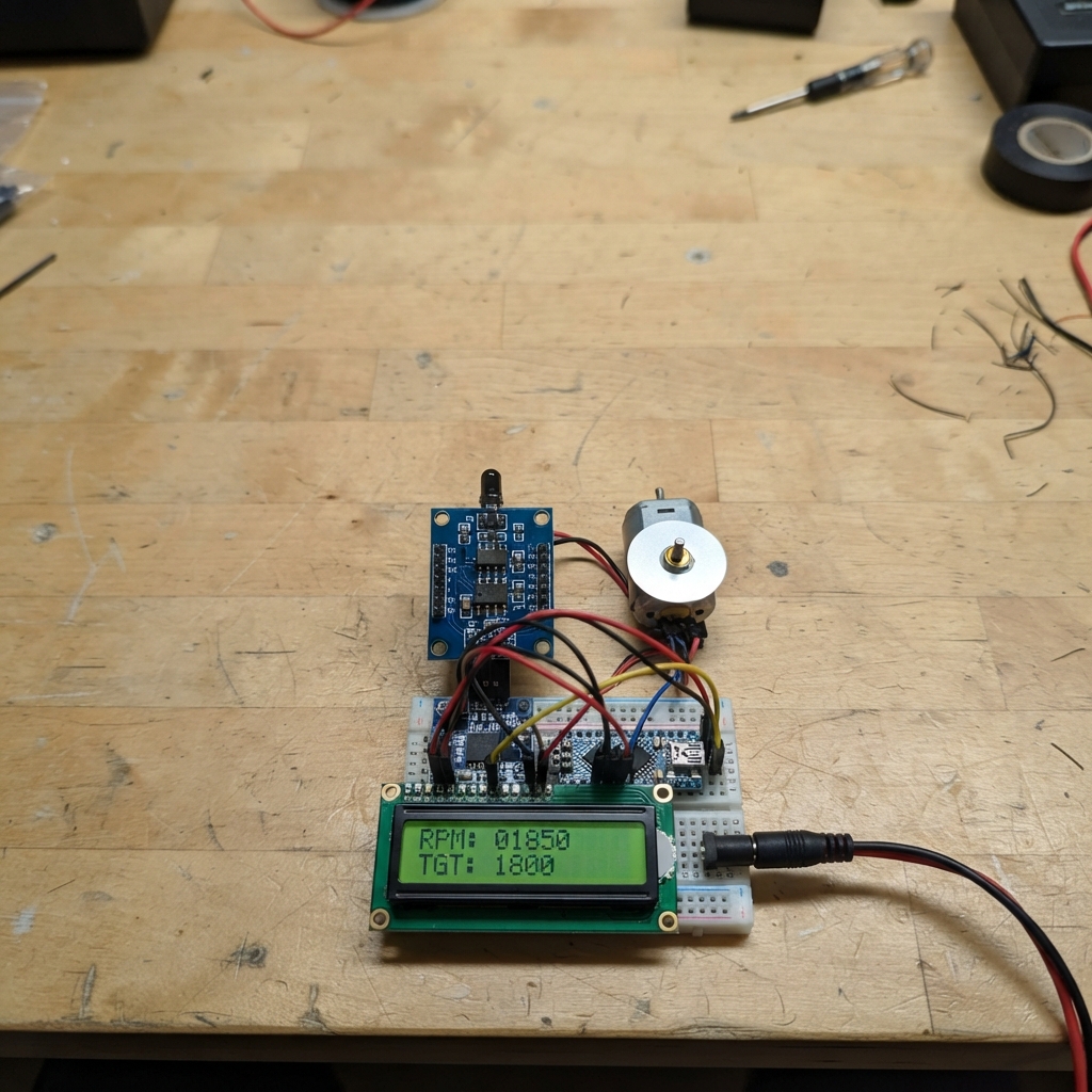
This project builds a real-time RPM tester for 12V motors using an ESP32 microcontroller and an infrared line tracking sensor to detect motor shaft rotation. The TCRT5000 sensor reads reflective marks on the spinning shaft, while dual displays (LCD 16x2 and SSD1306 OLED) show the current speed simultaneously. A logic level shifter bridges the 3.3V ESP32 and 5V sensor signals safely.
The guide includes a complete wiring diagram showing sensor connections with protective resistors, I2C display wiring, and power distribution from a 12V barrel jack. Assembly steps cover sensor placement and calibration, while the provided firmware handles pulse counting and dual-display output at one-second intervals. Builders will have everything needed to monitor motor performance during testing or troubleshooting.
Wiring diagram
Gather all the parts
Assemble it in 6 steps
1. Place the speed marker
Clean a flat rotating face on the motor shaft, coupling, or a disk fixed to the shaft. Add one narrow bright reflective tape strip and leave the rest of that face dark; this makes one pulse for each complete turn.
- A white or silver strip about 5 mm wide is enough. Matte black tape around it helps if the rest of the surface is shiny.
- Keep tape and any added disk clear of fingers, wires, and the motor body; loose tape can fly off when the motor spins.
2. Wire the 5 V and 3.3 V converter
Connect logic_shifter HV to the ESP32 5V/VIN pin (5 V supply), LV to ESP32 3V3 (3.3 V supply), and GND to an ESP32 GND pin (ground). This small board keeps the 5 V LCD signals away from the ESP32 pins.
- Do not swap the HV and LV power connections; sending 5 V into an ESP32 signal pin can permanently damage it.
3. Wire the RPM sensor and its safety resistors
Connect rpm_sensor VCC to ESP32 5V/VIN (power) and rpm_sensor GND to ESP32 GND (ground). Connect rpm_sensor DO to sensor_divider_high P1 (signal). Join sensor_divider_high P2, sensor_divider_low P1, and ESP32 GPIO27 together (the safe pulse signal). Connect sensor_divider_low P2 to ESP32 GND (ground). Leave the sensor AO pin unconnected.
- Use the 10 kΩ resistor for sensor_divider_high and the 20 kΩ resistor for sensor_divider_low. Aim the two small sensor windows at the tape about 2–10 mm away.
- Do not connect the sensor DO pin directly to GPIO27; its 5 V signal can damage the ESP32. Keep the sensor clear of the spinning shaft.
4. Wire both speed screens
For the 16×2 LCD, connect rpm_lcd VCC to ESP32 5V/VIN (power), rpm_lcd GND to ESP32 GND (ground), rpm_lcd SDA to logic_shifter HV1 (data), logic_shifter LV1 to ESP32 GPIO21 (data), rpm_lcd SCL to logic_shifter HV2 (clock), and logic_shifter LV2 to ESP32 GPIO22 (clock). For rpm_oled, connect VCC to ESP32 3V3 (power), GND to ESP32 GND (ground), SDA to the same logic_shifter LV1 connection (data), and SCL to the same logic_shifter LV2 connection (clock).
- The OLED header is commonly labelled GND, VCC, SCL, SDA; read the printing on your module because some look-alike boards swap the order. If the LCD lights but has no letters, slowly turn the tiny contrast screw on its back.
- Make sure VCC and GND are not swapped on either screen; swapped power can damage a screen. The OLED must use ESP32 3V3, not the LCD's 5 V side.
5. Power the motor separately
With motor_supply unplugged from the wall, connect motor_supply +12V to the 12 V motor positive terminal (motor power) and motor_supply GND to the motor negative terminal (motor return). Power the ESP32 separately from its USB socket; do not connect the adapter's 12 V wire to any ESP32 pin.
- Secure the motor so it cannot roll or twist when it starts.
- The adapter can deliver enough current to heat a shorted wire or destroy the ESP32 if 12 V reaches the board. Unplug it before moving motor wiring.
6. Set the sensor distance
Hold the sensor so its windows face the marked rotating surface without touching it, then secure it with tape, a clamp, or a small bracket. Start the motor and adjust the sensor's small screw until the RPM value stays steady on both screens.
- The tester expects one bright tape mark. With two marks, it will display twice the real RPM until the firmware is changed.
- Keep hands, clothing, and sensor leads away from the spinning motor and shaft.
Review all connections
1. Connections between "rpm_sensor" and "ESP32"
2. Connections between "sensor_divider_high" and "ESP32"
3. Connections between "sensor_divider_low" and "ESP32"
4. Connections between "rpm_lcd" and "ESP32"
5. Connections between "logic_shifter" and "ESP32"
6. Connections between "motor_supply" and "ESP32"
7. Connections between "rpm_oled" and "ESP32"
Deploy the firmware
#include <Wire.h>
#include <LiquidCrystal_I2C.h>
#include <Adafruit_GFX.h>
#include <Adafruit_SSD1306.h>

const uint8_t SENSOR_PIN = 27;
const uint8_t I2C_SDA_PIN = 21;
const uint8_t I2C_SCL_PIN = 22;
const uint32_t SAMPLE_INTERVAL_MS = 1000;
const uint8_t MARKS_PER_REVOLUTION = 1;

LiquidCrystal_I2C lcd(0x27, 16, 2);
Adafruit_SSD1306 oled(128, 64, &Wire, -1);
bool oledReady = false;
volatile uint32_t pulseCount = 0;
uint32_t lastSampleMs = 0;
long lastDisplayedRpm = -1;

void IRAM_ATTR countPulse() {
  pulseCount++;
}

void showRpm(uint32_t rpm) {
  lcd.setCursor(0, 0);
  lcd.print("Motor speed:    ");
  lcd.setCursor(0, 1);
  lcd.print(rpm);
  lcd.print(" RPM       ");

  if (oledReady) {
    oled.clearDisplay();
    oled.setTextSize(1);
    oled.setCursor(0, 0);
    oled.print("12V MOTOR SPEED");
    oled.drawFastHLine(0, 12, 128, SSD1306_WHITE);
    oled.setTextSize(3);
    oled.setCursor(0, 23);
    oled.print(rpm);
    oled.setTextSize(1);
    oled.print(" RPM");
    oled.display();
  }
}

void setup() {
  pinMode(SENSOR_PIN, INPUT);
  Wire.begin(I2C_SDA_PIN, I2C_SCL_PIN);
  lcd.init();
  lcd.backlight();
  lcd.setCursor(0, 0);
  lcd.print("Motor RPM tester");
  lcd.setCursor(0, 1);
  lcd.print("Waiting...      ");

  oledReady = oled.begin(SSD1306_SWITCHCAPVCC, 0x3C);
  if (oledReady) {
    oled.clearDisplay();
    oled.setTextColor(SSD1306_WHITE);
    oled.setTextSize(1);
    oled.setCursor(0, 0);
    oled.print("12V MOTOR SPEED");
    oled.setCursor(0, 22);
    oled.print("Waiting for pulse...");
    oled.display();
  }

  attachInterrupt(digitalPinToInterrupt(SENSOR_PIN), countPulse, FALLING);
  lastSampleMs = millis();
}

void loop() {
  const uint32_t now = millis();
  const uint32_t elapsedMs = now - lastSampleMs;

  if (elapsedMs >= SAMPLE_INTERVAL_MS) {
    noInterrupts();
    const uint32_t pulses = pulseCount;
    pulseCount = 0;
    interrupts();

    const uint32_t rpm = (uint32_t)pulses * 60000UL /
                         (elapsedMs * MARKS_PER_REVOLUTION);
    if ((long)rpm != lastDisplayedRpm) {
      showRpm(rpm);
      lastDisplayedRpm = rpm;
    }
    lastSampleMs = now;
  }

  delay(5);
}
Remix this project
Make it yours in one click
Open a full copy of this project in your own Schematik workspace, diagram, code, parts, and assembly steps included. Swap the sensor, add features, or redesign the whole thing with AI. The author's original stays untouched.