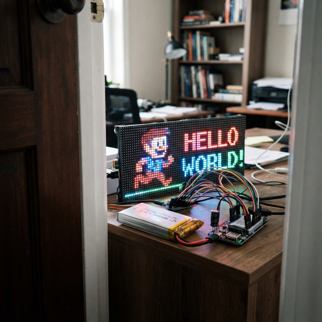
Build a 64x64 RGB LED matrix display that animates colorful orbs bouncing across a grid backdrop. This project combines an ESP32 microcontroller with a HUB75 LED panel, powered by a rechargeable LiPo battery and USB-C charging module for portable operation.
This guide provides a complete wiring diagram, parts list, and pre-written firmware using the Adafruit Protomatter library. Assembly takes just minutes—mount the MatrixPortal adapter to the LED panel, connect the battery to the charging module, wire the panel to power, and connect the controller to the battery. The included code demonstrates smooth animation with collision detection and customizable orb behavior, ready to modify for different effects.
Wiring diagram
Gather all the parts
Assemble it in 5 steps
1. MatrixPortal auf das Panel setzen
Lege das 64×64-Panel mit der Anschlusseite nach oben hin. Stecke den 2×8-HUB75-Stecker des MatrixPortal S3 gerade auf den HUB75-Eingang des Panels, oder verwende das beiliegende 16-polige Flachbandkabel. Die rote Kante des Kabels muss an beiden Enden bei Pin 1 liegen.
- Der Stecker darf nicht um eine Reihe versetzt sitzen; der MatrixPortal-Stecker ist dafür breiter als die Panelbuchse.
- Ein verdrehtes oder um eine Reihe versetztes Flachbandkabel zeigt kein richtiges Bild und kann das Panel beschädigen.
2. Akku an das Lademodul anschließen
Verbinde BAT+ des 1S-LiPo-Akkus mit B+ am IP5328P-Modul und BAT− mit B−. Nutze den passenden Akkuanschluss oder isoliere jede Lötstelle einzeln mit Schrumpfschlauch.
- Vertauschte Akkuadern können Akku und Lademodul beschädigen. Niemals kurzzeitig Plus und Minus berühren lassen.
3. Panel direkt mit 5 V versorgen
Verbinde 5V OUT des IP5328P mit VCC des Panels und GND OUT mit GND des Panels. Verwende für diese zwei Leitungen kurze, dicke Kabel. Stecke den 1000-µF-Kondensator parallel nahe am Panel an: sein längeres Bein mit Plus an VCC, die Seite mit dem Minusstreifen an GND.
- Der Kondensator hilft gegen Flackern, wenn viele LEDs zugleich aufleuchten.
- Der Minusstreifen am Kondensator muss an GND liegen; falsch herum kann der Kondensator heiß werden oder platzen. Das Panel darf nie am 3V3-Anschluss des Controllers hängen.
4. Controller vom Akku speisen
Verbinde 5 V vom USB-C-Ausgang des IP5328P mit einem kurzen USB-C-Kabel mit der USB-C-Buchse des MatrixPortal S3. Das Panel bleibt trotzdem an seinen eigenen dicken 5-V- und GND-Kabeln aus Schritt 3.
- Wenn der Akku das MatrixPortal über USB-C versorgt, darf nicht gleichzeitig ein Computer-USB-Kabel angeschlossen sein; zwei 5-V-Quellen gegeneinander können Geräte beschädigen.
5. Zum Programmieren umstecken
Ziehe für das Programmieren das USB-C-Kabel vom Akkumodul zum MatrixPortal ab. Schließe danach nur den Computer per USB-C am MatrixPortal an. Nach dem Übertragen ziehst du das Computerkabel wieder ab und steckst das Akkukabel erneut ein.
- Das Panel darf beim Programmieren weiter aus seinem eigenen 5-V-Stromweg versorgt bleiben.
Review all connections
1. Connections between "battery_1s_5000" and "ESP32"
2. Connections between "powerbank_module" and "ESP32"
3. Connections between "supply_capacitor" and "ESP32"
4. Connections between "matrix_64x64" and "ESP32"
Deploy the firmware
#include <Arduino.h>
#include <Adafruit_GFX.h>
#include <Adafruit_Protomatter.h>

constexpr uint16_t PANEL_WIDTH = 64;
constexpr uint16_t PANEL_HEIGHT = 64;
// Four-bit color depth reduces current compared with a maximum-brightness panel mode.
constexpr uint32_t FRAME_INTERVAL_MS = 50;

// Fixed MatrixPortal S3 HUB75 wiring; do not connect these pins manually.
uint8_t rgbPins[] = {42, 41, 40, 38, 39, 37};
uint8_t addrPins[] = {45, 36, 48, 35, 21};
constexpr uint8_t CLOCK_PIN = 2;
constexpr uint8_t LATCH_PIN = 47;
constexpr uint8_t OUTPUT_ENABLE_PIN = 14;

Adafruit_Protomatter matrix(
  PANEL_WIDTH, 4, 1, rgbPins, 5, addrPins,
  CLOCK_PIN, LATCH_PIN, OUTPUT_ENABLE_PIN, false);

struct Orb {
  float x;
  float y;
  float dx;
  float dy;
  int16_t radius;
  uint16_t color;
};

Orb orbs[] = {
  {10.0f, 12.0f,  0.95f,  0.70f, 6, 0xF800},
  {50.0f, 14.0f, -0.80f,  0.92f, 5, 0x07E0},
  {18.0f, 48.0f,  0.72f, -0.86f, 7, 0x001F},
  {48.0f, 46.0f, -0.90f, -0.63f, 4, 0xFFE0}
};
constexpr size_t ORB_COUNT = sizeof(orbs) / sizeof(orbs[0]);
constexpr uint16_t GRID_COLOR = 0x0001;
uint32_t lastFrameMs = 0;

void drawGrid() {
  for (int16_t y = 0; y < PANEL_HEIGHT; y += 8) {
    matrix.drawFastHLine(0, y, PANEL_WIDTH, GRID_COLOR);
  }
  for (int16_t x = 0; x < PANEL_WIDTH; x += 8) {
    matrix.drawFastVLine(x, 0, PANEL_HEIGHT, GRID_COLOR);
  }
}

void restoreGridUnder(const Orb &orb) {
  const int16_t left = max<int16_t>(0, static_cast<int16_t>(orb.x) - orb.radius);
  const int16_t right = min<int16_t>(PANEL_WIDTH - 1, static_cast<int16_t>(orb.x) + orb.radius);
  const int16_t top = max<int16_t>(0, static_cast<int16_t>(orb.y) - orb.radius);
  const int16_t bottom = min<int16_t>(PANEL_HEIGHT - 1, static_cast<int16_t>(orb.y) + orb.radius);

  for (int16_t y = ((top + 7) / 8) * 8; y <= bottom; y += 8) {
    matrix.drawFastHLine(left, y, right - left + 1, GRID_COLOR);
  }
  for (int16_t x = ((left + 7) / 8) * 8; x <= right; x += 8) {
    matrix.drawFastVLine(x, top, bottom - top + 1, GRID_COLOR);
  }
}

void eraseOldOrbs() {
  for (size_t i = 0; i < ORB_COUNT; ++i) {
    matrix.fillCircle(static_cast<int16_t>(orbs[i].x), static_cast<int16_t>(orbs[i].y), orbs[i].radius, 0);
    restoreGridUnder(orbs[i]);
  }
}

void moveOrb(Orb &orb) {
  orb.x += orb.dx;
  orb.y += orb.dy;
  if (orb.x - orb.radius < 0 || orb.x + orb.radius >= PANEL_WIDTH) {
    orb.dx = -orb.dx;
    orb.x = constrain(orb.x, static_cast<float>(orb.radius), static_cast<float>(PANEL_WIDTH - 1 - orb.radius));
  }
  if (orb.y - orb.radius < 0 || orb.y + orb.radius >= PANEL_HEIGHT) {
    orb.dy = -orb.dy;
    orb.y = constrain(orb.y, static_cast<float>(orb.radius), static_cast<float>(PANEL_HEIGHT - 1 - orb.radius));
  }
}

void drawOrbs() {
  for (size_t i = 0; i < ORB_COUNT; ++i) {
    matrix.fillCircle(static_cast<int16_t>(orbs[i].x), static_cast<int16_t>(orbs[i].y), orbs[i].radius, orbs[i].color);
  }
}

void setup() {
  if (matrix.begin() != PROTOMATTER_OK) {
    while (true) delay(1000);
  }
  matrix.fillScreen(0);
  drawGrid();
  drawOrbs();
}

void loop() {
  const uint32_t now = millis();
  const uint32_t elapsed = now - lastFrameMs;
  if (elapsed < FRAME_INTERVAL_MS) {
    delay(FRAME_INTERVAL_MS - elapsed);
    return;
  }

  lastFrameMs = now;
  eraseOldOrbs();
  for (size_t i = 0; i < ORB_COUNT; ++i) moveOrb(orbs[i]);
  drawOrbs();
}
Remix this project
Make it yours in one click
Open a full copy of this project in your own Schematik workspace, diagram, code, parts, and assembly steps included. Swap the sensor, add features, or redesign the whole thing with AI. The author's original stays untouched.