Community project
3D Printed Macro Pad
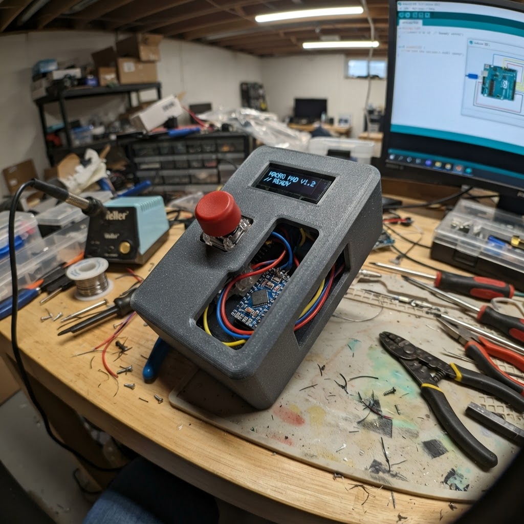
This project builds a 6-button macro pad using a Raspberry Pi Pico microcontroller and 3D-printed enclosure. The pad supports hot-swap mechanical switches and can be reconfigured to send any F13-F24 key combination, making it ideal for triggering macros in creative software, games, or productivity applications.
The guide includes a complete wiring diagram showing how to connect each button to the Pico's GPIO pins with a common ground configuration, a parts list with recommended components, and step-by-step assembly instructions for printing and preparing the case. The included firmware handles debouncing, stores custom key mappings in the Pico's flash memory, and provides a serial interface for reprogramming the pad without reflashing.
Wiring diagram

Gather all the parts
Assemble it in 5 steps
1. Print and prepare the enclosure
Print the 2 × 3 top plate, bottom shell, six keycaps, and a USB opening sized for the Raspberry Pi Pico. Test-fit the Pico and USB cable before installing electronics.
- Use a 0.2 mm layer height for keycaps and plate.
- Leave clearance around the USB connector so the cable is not stressed.
- Do not force the Pico or USB plug into a tight printed opening.
2. Install hot-swap sockets and switches
Press each MX hot-swap socket into the underside of the printed plate, then insert the six MX switches from above. Label physical positions 1–6 from left to right, top row then bottom row.
- Test that every switch clicks and sits flat before attaching wires.
- Hot-swap sockets let switches be removed later without desoldering.
- Each switch has two electrical contacts; do not connect both contacts directly together.
3. Create the common ground wire
Daisy-chain one contact of every switch using a single insulated wire, then connect that common wire to a GND pin on the Pico.
- Pre-crimped Dupont leads or a small terminal block can reduce soldering at the Pico.
- Keep the ground wire routed around the perimeter of the plate.
- Unplug the Pico from USB while fitting or soldering wires.
4. Wire the six signal contacts
Connect the unused contact of each switch to the Pico: key 1→GP2, key 2→GP3, key 3→GP4, key 4→GP5, key 5→GP6, key 6→GP7. These direct connections eliminate the need for a matrix or diodes.
- Use different wire colors or small labels for GP2 through GP7.
- Tug-test each connection gently before closing the case.
- Never connect a switch signal wire to 3V3, 5V, or VSYS; it must connect only to its named GPIO.
5. Close the case and configure the pad
Mount the Pico in the shell, fit the keycaps, and connect USB. Deploy the firmware with Schematik’s Deploy button. Then run data/macro_pad_remapper.py on a computer with Python/Tkinter and pyserial, select the Pico serial port, choose F13–F24 for each displayed key, and click Save mapping to pad.
- Default assignments are F13, F14, F15, F16, F17, and F18.
- The saved mapping remains in the Pico after USB power is removed; games can bind those uncommon function keys directly.
- The remapper must be closed before another application can use the Pico serial port.
Review all connections
1. Connections between "key_1" and "Raspberry Pi Pico"
2. Connections between "key_2" and "Raspberry Pi Pico"
3. Connections between "key_3" and "Raspberry Pi Pico"
4. Connections between "key_4" and "Raspberry Pi Pico"
5. Connections between "key_5" and "Raspberry Pi Pico"
6. Connections between "key_6" and "Raspberry Pi Pico"
Deploy the firmware
#include <Arduino.h>
#include <Keyboard.h>
#include <EEPROM.h>


// Hoisted type definitions
struct PadConfig {
  uint32_t magic;
  uint8_t functionNumber[KEY_COUNT];
};


// Forward declarations
uint8_t defaultFunctionNumber(uint8_t index);
bool validFunctionNumber(int number);
uint8_t hidKeyForFunction(uint8_t number);
void saveConfig();
void loadConfig();
void sendMap();
void handleCommand(char *command);
void serviceSerial();
void sendMappedKey(uint8_t index);

const uint8_t keyPins[] = {2, 3, 4, 5, 6, 7};
const uint8_t KEY_COUNT = 6;
const unsigned long DEBOUNCE_MS = 20;

// Python GUI protocol: GET, SET <1-6> <13-24>, RESET.
// The map is retained in the Pico's flash-backed EEPROM emulation.
const uint32_t CONFIG_MAGIC = 0x4D504144;

PadConfig config;

bool stablePressed[KEY_COUNT] = {};
bool lastSample[KEY_COUNT] = {};
unsigned long lastChangeMs[KEY_COUNT] = {};
char commandBuffer[48];
uint8_t commandLength = 0;

uint8_t defaultFunctionNumber(uint8_t index) { return 13 + index; }
bool validFunctionNumber(int number) { return number >= 13 && number <= 24; }

uint8_t hidKeyForFunction(uint8_t number) {
  switch (number) {
    case 13: return KEY_F13; case 14: return KEY_F14; case 15: return KEY_F15;
    case 16: return KEY_F16; case 17: return KEY_F17; case 18: return KEY_F18;
    case 19: return KEY_F19; case 20: return KEY_F20; case 21: return KEY_F21;
    case 22: return KEY_F22; case 23: return KEY_F23; case 24: return KEY_F24;
    default: return KEY_F13;
  }
}

void saveConfig() {
  EEPROM.put(0, config);
  EEPROM.commit();
}

void loadConfig() {
  EEPROM.begin(sizeof(PadConfig));
  EEPROM.get(0, config);
  if (config.magic != CONFIG_MAGIC) {
    config.magic = CONFIG_MAGIC;
    for (uint8_t i = 0; i < KEY_COUNT; ++i) config.functionNumber[i] = defaultFunctionNumber(i);
    saveConfig();
  }
  for (uint8_t i = 0; i < KEY_COUNT; ++i) {
    if (!validFunctionNumber(config.functionNumber[i])) config.functionNumber[i] = defaultFunctionNumber(i);
  }
}

void sendMap() {
  Serial.print("MAP ");
  for (uint8_t i = 0; i < KEY_COUNT; ++i) {
    if (i) Serial.print(',');
    Serial.print(config.functionNumber[i]);
  }
  Serial.println();
}

void handleCommand(char *command) {
  if (!strcmp(command, "GET")) { sendMap(); return; }
  if (!strcmp(command, "RESET")) {
    for (uint8_t i = 0; i < KEY_COUNT; ++i) config.functionNumber[i] = defaultFunctionNumber(i);
    saveConfig();
    Serial.println("OK RESET");
    return;
  }
  int keyNumber, functionNumber;
  if (sscanf(command, "SET %d %d", &keyNumber, &functionNumber) == 2 &&
      keyNumber >= 1 && keyNumber <= KEY_COUNT && validFunctionNumber(functionNumber)) {
    config.functionNumber[keyNumber - 1] = functionNumber;
    saveConfig();
    Serial.println("OK SET");
    return;
  }
  Serial.println("ERR Use GET, SET <1-6> <13-24>, or RESET");
}

void serviceSerial() {
  while (Serial.available()) {
    char c = (char)Serial.read();
    if (c == '\r') continue;
    if (c == '\n') {
      commandBuffer[commandLength] = '\0';
      if (commandLength) handleCommand(commandBuffer);
      commandLength = 0;
    } else if (commandLength < sizeof(commandBuffer) - 1) {
      commandBuffer[commandLength++] = c;
    } else {
      commandLength = 0;
      Serial.println("ERR Command too long");
    }
  }
}

void sendMappedKey(uint8_t index) {
  Keyboard.press(hidKeyForFunction(config.functionNumber[index]));
  delay(8);
  Keyboard.releaseAll();
}

void setup() {
  loadConfig();
  for (uint8_t i = 0; i < KEY_COUNT; ++i) {
    pinMode(keyPins[i], INPUT_PULLUP);
    stablePressed[i] = lastSample[i] = (digitalRead(keyPins[i]) == LOW);
  }
  Serial.begin(115200);
  Keyboard.begin();
}

void loop() {
  serviceSerial();
  unsigned long now = millis();
  for (uint8_t i = 0; i < KEY_COUNT; ++i) {
    bool samplePressed = (digitalRead(keyPins[i]) == LOW);
    if (samplePressed != lastSample[i]) {
      lastSample[i] = samplePressed;
      lastChangeMs[i] = now;
    }
    if (now - lastChangeMs[i] >= DEBOUNCE_MS && samplePressed != stablePressed[i]) {
      stablePressed[i] = samplePressed;
      if (stablePressed[i]) sendMappedKey(i);
    }
  }
}
Remix this project
Make it yours in one click
Open a full copy of this project in your own Schematik workspace — diagram, code, parts, and assembly steps included. Swap the sensor, add features, or redesign the whole thing with AI. The author's original stays untouched.
Related projects
Fridge Scale Smart Clip
Raspberry Pi Pico · September 14, 2026Phillip Knopp
Tiny Robot AI Assistant
Raspberry Pi Pico · September 13, 2026Shaikh Tajmul haque
Tiny Spider Robot
Raspberry Pi Pico · September 13, 2026Shaikh Tajmul haque