Community project
Medication Confirmation Reminder
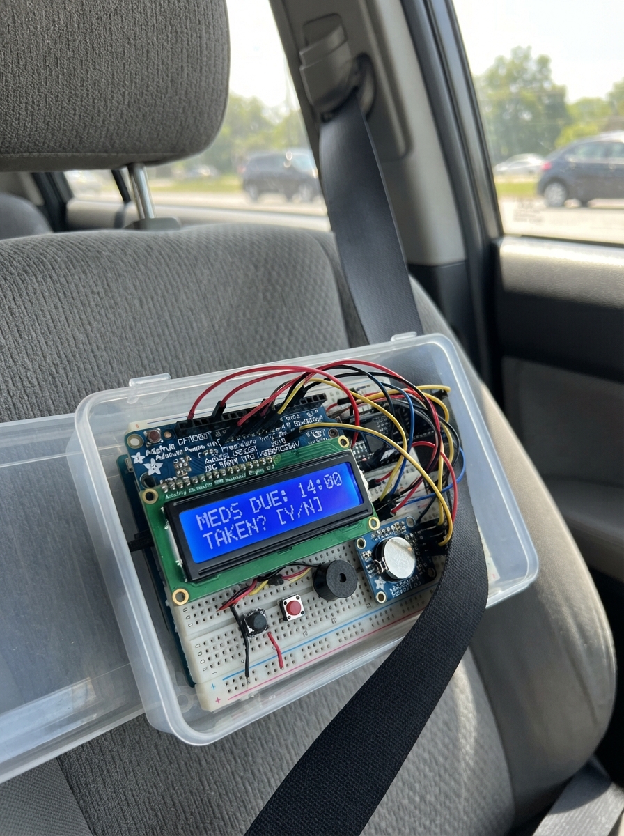
This medication reminder system uses a Raspberry Pi Pico to track and alert users when it's time to take their medication. The device combines a real-time clock for accurate scheduling, an I2C LCD display to show current time and dose information, a buzzer for audio alerts, and non-volatile memory to log every confirmed dose. Three buttons allow users to set medication times, navigate through the interface, and confirm when a dose has been taken.
This guide provides a complete parts list, wiring diagram showing all I2C and GPIO connections, step-by-step assembly instructions, and the full firmware needed to run the reminder system. Builders will learn how to interface multiple I2C devices on a single bus, implement debounced button input, manage real-time scheduling, and store medication history in persistent memory.
Wiring diagram

Gather all the parts
Assemble it in 5 steps
1. Coloca las piezas en el frente
Monta la pantalla LCD de 16×2 en el hueco inclinado de la caja. Coloca el botón grande confirm_button centrado al frente; es el único que detiene el sonido. Coloca set_button y next_button junto a él y deja la rejilla del buzzer libre.
- Usa letras grandes y alto contraste: «CONFIRMAR» en el botón grande, «AJUSTAR» y «SIGUIENTE» en los pequeños.
- La inclinación aproximada de 15° hace que la hora se lea sentado.
- No tapes la salida del buzzer: el sonido debe poder oírse desde otra habitación.
2. Conecta la alimentación común
Con la Raspberry Pi Pico sin conectar al USB, une el pin 3V3 del Pico al VIN del rtc_ds3231, al VCC del lcd_16x2 y al VIN del log_fram (alimentación). Une un pin GND del Pico al GND de cada uno de esos tres módulos, al GND del alarm_buzzer y a una pata de cada botón (tierra).
- Puedes distribuir 3V3 y GND con dos filas de una placa perforada o una regleta; todos los GND deben quedar unidos.
- No conectes VCC a 5 V: este montaje usa 3,3 V para proteger las entradas del Pico.
3. Une reloj, pantalla y memoria
Conecta SDA del rtc_ds3231, lcd_16x2 y log_fram juntos a GP4 del Pico (datos). Conecta SCL de los tres módulos juntos a GP5 del Pico (reloj de datos). Inserta una pila de respaldo compatible en el rtc_ds3231 si tu módulo dispone de portapila; así la hora no se pierde al desenchufarlo.
- Los tres módulos comparten los mismos dos cables de datos; no necesitan un pin distinto cada uno.
- El RTC conserva la hora; la FRAM conserva el historial de confirmaciones.
- Asegúrate de no intercambiar SDA y SCL; la pantalla puede quedar en blanco si se cruzan.
4. Cablea el sonido y los tres botones
Conecta SIGNAL del alarm_buzzer a GP6 del Pico (sonido). Conecta la pata libre de confirm_button a GP7 (confirmación), la de set_button a GP8 (ajuste) y la de next_button a GP9 (siguiente). Cada otra pata de botón ya va a GND; el programa usa esa conexión para que una pulsación cuente una sola vez.
- El botón grande debe ser normalmente abierto: al soltarlo no debe haber continuidad entre sus patas.
- Si el buzzer tiene marcas + y −, conecta la entrada marcada + o SIGNAL a GP6 y la marcada − a GND.
- No uses un buzzer de más de 3,3 V directamente en GP6; usa un modelo activo compatible con 3,3 V o añade un transistor de control en la revisión de PCB.
5. Fija y revisa antes de cerrar
Atornilla el Pico y los módulos a separadores M3 dentro de la caja, sin que las soldaduras toquen la carcasa ni otras placas. Revisa una vez más cada cable contra el diagrama, cierra la tapa y conecta el Pico al ordenador solo por USB.
- Deja accesible el puerto USB para cargar el programa y para que el cuidador pueda obtener el historial.
- Tras encender, usa AJUSTAR para recorrer hora y minutos de tres horarios; SIGUIENTE aumenta el valor.
- Un cable de 3,3 V conectado por error a GND puede calentar o dañar la placa; revisa antes de enchufar el USB.
Review all connections
1. Connections between "rtc_ds3231" and "Raspberry Pi Pico"
2. Connections between "alarm_buzzer" and "Raspberry Pi Pico"
3. Connections between "confirm_button" and "Raspberry Pi Pico"
4. Connections between "set_button" and "Raspberry Pi Pico"
5. Connections between "next_button" and "Raspberry Pi Pico"
6. Connections between "lcd_16x2" and "Raspberry Pi Pico"
7. Connections between "log_fram" and "Raspberry Pi Pico"
Deploy the firmware
#include <Wire.h>
#include <RTClib.h>
#include <Adafruit_FRAM_I2C.h>
#include <DFRobot_RGBLCD1602.h>

const uint8_t I2C_SDA_PIN = 4;
const uint8_t I2C_SCL_PIN = 5;
const uint8_t BUZZER_PIN = 6;
const uint8_t CONFIRM_PIN = 7;
const uint8_t SET_PIN = 8;
const uint8_t NEXT_PIN = 9;
const uint8_t DOSES_PER_DAY = 3;

uint8_t doseHour[DOSES_PER_DAY] = {8, 13, 20};
uint8_t doseMinute[DOSES_PER_DAY] = {0, 0, 0};
RTC_DS3231 rtc;
Adafruit_FRAM_I2C fram;
DFRobot_RGBLCD1602 lcd(0x60, 16, 2);

struct Button { uint8_t pin; bool stable = HIGH; bool raw = HIGH; unsigned long changedAt = 0; };
Button confirmButton{CONFIRM_PIN}, setButton{SET_PIN}, nextButton{NEXT_PIN};
bool alarmActive = false, framPresent = false, configuring = false;
int8_t activeDose = -1;
bool doseTriggered[DOSES_PER_DAY] = {false, false, false};
uint8_t lastDay = 0, configDose = 0, configField = 0;
unsigned long lastScreenAt = 0;
String lastLine1, lastLine2;
const uint16_t FRAM_MAGIC_ADDR = 0, FRAM_COUNT_ADDR = 2, FRAM_LOG_ADDR = 16;
const uint8_t LOG_RECORD_SIZE = 8;
const uint16_t MAX_LOGS = 4000;

bool pressed(Button &b) {
  bool raw = digitalRead(b.pin); unsigned long now = millis();
  if (raw != b.raw) { b.raw = raw; b.changedAt = now; }
  if (now - b.changedAt > 35 && raw != b.stable) { b.stable = raw; return b.stable == LOW; }
  return false;
}
String two(uint8_t n) { return n < 10 ? "0" + String(n) : String(n); }
String pad16(String s) { while (s.length() < 16) s += ' '; return s.substring(0, 16); }
void showScreen(const String &a, const String &b, bool force = false) {
  String x = pad16(a), y = pad16(b);
  if (force || x != lastLine1) { lcd.setCursor(0, 0); lcd.print(x); lastLine1 = x; }
  if (force || y != lastLine2) { lcd.setCursor(0, 1); lcd.print(y); lastLine2 = y; }
}
void initializeLog() {
  if (fram.read(FRAM_MAGIC_ADDR) != 0x4D || fram.read(FRAM_MAGIC_ADDR + 1) != 0x52) {
    fram.write(FRAM_MAGIC_ADDR, 0x4D); fram.write(FRAM_MAGIC_ADDR + 1, 0x52);
    fram.write(FRAM_COUNT_ADDR, 0); fram.write(FRAM_COUNT_ADDR + 1, 0);
  }
}
uint16_t logCount() { return uint16_t(fram.read(FRAM_COUNT_ADDR)) | (uint16_t(fram.read(FRAM_COUNT_ADDR + 1)) << 8); }
void setLogCount(uint16_t c) { fram.write(FRAM_COUNT_ADDR, c & 0xFF); fram.write(FRAM_COUNT_ADDR + 1, c >> 8); }
void writeLog(uint8_t dose, const DateTime &now) {
  if (!framPresent) return;
  uint16_t count = logCount(), address = FRAM_LOG_ADDR + (count % MAX_LOGS) * LOG_RECORD_SIZE;
  uint32_t stamp = now.unixtime();
  for (uint8_t i = 0; i < 4; i++) fram.write(address + i, (stamp >> (8 * i)) & 0xFF);
  fram.write(address + 4, dose); fram.write(address + 5, 0xA5); fram.write(address + 6, (stamp ^ dose) & 0xFF); fram.write(address + 7, 0x5A);
  setLogCount(count == 65535 ? 0 : count + 1);
  Serial.print("CONFIRMADA,"); Serial.print(now.timestamp(DateTime::TIMESTAMP_FULL)); Serial.print(",dosis "); Serial.println(dose + 1);
}
void printLog() {
  if (!framPresent) { Serial.println("FRAM no disponible"); return; }
  uint16_t count = logCount(), entries = count < MAX_LOGS ? count : MAX_LOGS, first = count < MAX_LOGS ? 0 : count % MAX_LOGS;
  Serial.println("LOG DE CONFIRMACIONES");
  for (uint16_t i = 0; i < entries; i++) {
    uint16_t a = FRAM_LOG_ADDR + ((first + i) % MAX_LOGS) * LOG_RECORD_SIZE;
    if (fram.read(a + 5) != 0xA5 || fram.read(a + 7) != 0x5A) continue;
    uint32_t stamp = uint32_t(fram.read(a)) | (uint32_t(fram.read(a + 1)) << 8) | (uint32_t(fram.read(a + 2)) << 16) | (uint32_t(fram.read(a + 3)) << 24);
    Serial.print(DateTime(stamp).timestamp(DateTime::TIMESTAMP_FULL)); Serial.print(",dosis "); Serial.println(fram.read(a + 4) + 1);
  }
}
void handleSerial() {
  if (!Serial.available()) return;
  String c = Serial.readStringUntil('\n'); c.trim(); c.toUpperCase();
  if (c == "LOG") printLog();
  else if (c.startsWith("SET ") && c.length() >= 23) {
    rtc.adjust(DateTime(c.substring(4,8).toInt(), c.substring(9,11).toInt(), c.substring(12,14).toInt(), c.substring(15,17).toInt(), c.substring(18,20).toInt(), c.substring(21,23).toInt()));
    Serial.println("RELOJ AJUSTADO");
  } else Serial.println("Comandos: LOG | SET AAAA-MM-DD HH:MM:SS");
}
void startAlarm(uint8_t dose) { alarmActive = true; activeDose = dose; lcd.setRGB(255, 0, 0); showScreen("TOME MEDICACION", "PULSE CONFIRMAR", true); Serial.print("ALARMA,dosis "); Serial.println(dose + 1); }
void stopAlarm(const DateTime &now) { noTone(BUZZER_PIN); writeLog(activeDose, now); alarmActive = false; activeDose = -1; lcd.setRGB(0, 180, 0); showScreen("Toma registrada", "Gracias", true); }
void checkSchedule(const DateTime &now) {
  if (now.day() != lastDay) { lastDay = now.day(); for (uint8_t i = 0; i < DOSES_PER_DAY; i++) doseTriggered[i] = false; }
  if (alarmActive || configuring) return;
  for (uint8_t i = 0; i < DOSES_PER_DAY; i++) if (!doseTriggered[i] && now.hour() == doseHour[i] && now.minute() == doseMinute[i]) { doseTriggered[i] = true; startAlarm(i); break; }
}
void handleConfiguration() {
  if (pressed(setButton)) {
    if (!configuring) { configuring = true; configDose = 0; configField = 0; lcd.setRGB(0, 0, 180); }
    else if (configField == 0) configField = 1;
    else if (configDose < DOSES_PER_DAY - 1) { configDose++; configField = 0; }
    else { configuring = false; lcd.setRGB(0, 120, 0); Serial.println("HORARIOS ACTUALIZADOS"); }
  }
  if (configuring && pressed(nextButton)) { if (configField == 0) doseHour[configDose] = (doseHour[configDose] + 1) % 24; else doseMinute[configDose] = (doseMinute[configDose] + 5) % 60; }
}
void updateDisplay(const DateTime &now) {
  if (alarmActive) return;
  if (configuring) { showScreen("Dosis " + String(configDose + 1) + (configField == 0 ? " hora" : " min"), two(doseHour[configDose]) + ":" + two(doseMinute[configDose]) + " SIG cambia"); return; }
  if (millis() - lastScreenAt < 1000) return;
  lastScreenAt = millis(); lcd.setRGB(0, 120, 0);
  showScreen(two(now.hour()) + ":" + two(now.minute()) + "  " + two(now.day()) + "/" + two(now.month()), "SET: horarios");
}
void setup() {
  pinMode(BUZZER_PIN, OUTPUT); pinMode(CONFIRM_PIN, INPUT_PULLUP); pinMode(SET_PIN, INPUT_PULLUP); pinMode(NEXT_PIN, INPUT_PULLUP);
  Serial.begin(115200); Wire.begin();
  lcd.init(); lcd.setRGB(0, 120, 0); showScreen("Recordatorio", "Iniciando...", true);
  if (!rtc.begin()) { lcd.setRGB(255, 0, 0); showScreen("RTC no detectado", "Revise cables", true); while (true) delay(100); }
  if (rtc.lostPower()) rtc.adjust(DateTime(F(__DATE__), F(__TIME__)));
  framPresent = fram.begin(0x50);
  if (framPresent) initializeLog(); else { lcd.setRGB(255, 120, 0); showScreen("FRAM no detectada", "Log no guardado", true); delay(1500); }
  lastDay = rtc.now().day(); Serial.println("LISTO. Comandos: LOG | SET AAAA-MM-DD HH:MM:SS");
}
void loop() {
  handleSerial(); DateTime now = rtc.now();
  if (alarmActive) { tone(BUZZER_PIN, 2400); if (pressed(confirmButton)) stopAlarm(now); return; }
  handleConfiguration(); checkSchedule(now); updateDisplay(now);
}
Remix this project
Make it yours in one click
Open a full copy of this project in your own Schematik workspace — diagram, code, parts, and assembly steps included. Swap the sensor, add features, or redesign the whole thing with AI. The author's original stays untouched.
Related projects

Orion Keyboard
Raspberry Pi Pico · October 11, 2026SGT Ishaan
Pico MIDI Controller
Raspberry Pi Pico · September 30, 2026stan_vandervoort
Drone Light Safety Controller (copy)
Raspberry Pi Pico · September 26, 2026ianlex.wip