Community project
Orion Keyboard
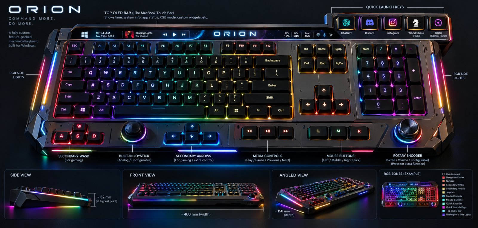
The Orion Keyboard is a 128-key programmable mechanical keyboard built around a Raspberry Pi Pico, featuring an integrated 0.96-inch OLED display, addressable RGB lighting, and analog input controls. This guide provides a complete wiring diagram, parts list, and step-by-step assembly instructions to build a fully functional keyboard with USB HID support, including key matrix scanning, joystick and rotary encoder input, and customizable per-key RGB effects.
The project demonstrates professional keyboard design patterns: I2C GPIO expansion for column scanning, proper debouncing and diode protection for the 8x16 key matrix, level-shifted RGB data signaling, and power management for LED chains. Builders will learn matrix keyboard architecture, I2C peripheral integration, USB HID firmware development, and how to add auxiliary control inputs to a Pico-based system.
Wiring diagram

Gather all the parts
Assemble it in 7 steps
1. Fit the controller and low-voltage parts
Place the Raspberry Pi Pico module, both MCP23017 chips, OLED connector, and the two I2C pull-up resistors in the controller area. Keep the Pico USB connector reachable at the rear edge; it is the only USB connection to the Windows PC. Place one 100 nF ceramic capacitor beside each MCP23017, one beside the OLED connector, and one beside the 74AHCT125 supply pins.
- Keep each small capacitor very close to the part it supports; it smooths brief power dips.
- Do not connect the separate RGB 5 V input to Pico 3V3 or VSYS. The Pico gets its own power through USB.
2. Wire the shared display and matrix-control wires
Connect Pico GP4 to SDA on both MCP23017 chips and the OLED (data). Connect Pico GP5 to SCL on both MCP23017 chips and the OLED (clock). Connect each 4.7 kΩ pull-up resistor between 3V3 and its SDA or SCL wire (keeps those two wires at a known safe state). Connect every MCP23017 and OLED VDD/VCC pin to 3V3 (power), and every VSS/GND pin to GND (ground).
- Use an OLED module specified for 3.3 V logic. If its board already has I2C pull-ups, fit only one effective pair of pull-ups on the completed bus.
- A module that pulls SDA or SCL up to 5 V can damage the Pico's 3.3 V input pins.
3. Build every key as a switch and diode pair
For every installed key, fit one switch and one 1N4148W diode. Wire the column net to the diode's unstriped anode end, wire the diode's striped cathode end to one switch terminal, and wire the other switch terminal to the row net. Use this exact direction for every installed key: COL → diode anode → striped cathode → switch → ROW. Connect ROW0 through ROW7 to Pico GP6 through GP13 (scan signals). Connect COL0 through COL7 to GPA0 through GPA7 on the first MCP23017 and COL8 through COL15 to GPA0 through GPA7 on the second MCP23017 (sense signals).
- Mark each fitted pair with a unique row/column reference, for example SW_R2_C5 and D_R2_C5. Empty matrix intersections receive no switch and no diode.
- The striped diode end must face the switch/row side. A reversed or missing diode causes unwanted key presses when several keys are held.
4. Connect the joystick and rotary control
Connect joystick VCC to 3V3 (power), GND to GND (ground), VRx to Pico GP26 (analog signal), VRy to Pico GP27 (analog signal), and SW to Pico GP22 (press signal). Connect rotary encoder C to GND (ground), A to GP14 (signal), and B to GP15 (signal). Wire its push switch through its own matrix diode between ROW7 and COL15 using the same column-to-row diode direction.
- The joystick and the dedicated middle button can both produce a middle click; the corrected firmware keeps the click held until both are released.
- Do not power the joystick from 5 V. Its analog outputs must never exceed the Pico's 3.3 V input limit.
5. Build the protected RGB power rail
Connect the locking connector +5V_IN to the resettable fuse IN (power), then fuse OUT to the protected RGB_5V rail (power). Connect the 1000 µF capacitor positive lead to RGB_5V and its striped negative lead to GND. Connect RGB_5V and GND to every WS2812B LED, with one 100 nF capacitor directly across RGB_5V and GND at each LED. Join the RGB supply ground to Pico ground through a wide, low-resistance ground connection.
- Use a regulated 5 V supply rated for at least 3 A. Use power pours or wide traces and inject RGB_5V/GND at several places along the full-size board.
- Reversing the RGB supply can damage all LEDs. The 1000 µF capacitor is polarized: its striped lead goes to ground.
6. Connect and terminate the RGB data buffer
Connect Pico GP16 to 74AHCT125 pin 1A (data), 1OE to GND (enables channel 1), VCC to RGB_5V (power), and GND to GND (ground). Connect 1Y to one end of the 330 Ω resistor, and the other end of that resistor to DIN on the first LED (data). Connect each LED DOUT to the next LED DIN. Connect unused 2A, 3A, and 4A inputs to GND. Connect unused active-low enables 2OE, 3OE, and 4OE through the 10 kΩ resistor array to RGB_5V so those three outputs stay disabled.
- Place the 330 Ω resistor close to the first LED and add a DOUT test pad at the last LED for later troubleshooting.
- Never connect 5 V LED data back into any Pico pin. GP16 only drives the 74AHCT125 input.
7. Connect an optional auxiliary control board
If the gaming controls are on a separate board, connect its row and column wires through the 2x12 connector using the matching labeled nets. Carry ROW0 through ROW7 and COL0 through COL15, and fit every auxiliary switch with its own diode in the same COL → diode → switch → ROW direction.
- Use keyed shrouded headers so the cable cannot be plugged in backwards.
- Do not plug or unplug an unshrouded auxiliary cable while power is connected; a slipped connector can short adjacent signals.
Review all connections
1. Connections between "matrix_columns_a" and "Raspberry Pi Pico"
2. Connections between "matrix_columns_b" and "Raspberry Pi Pico"
3. Connections between "key_matrix" and "Raspberry Pi Pico"
4. Connections between "oled_1" and "Raspberry Pi Pico"
5. Connections between "i2c_pullups" and "Raspberry Pi Pico"
6. Connections between "joystick_1" and "Raspberry Pi Pico"
7. Connections between "encoder_1" and "Raspberry Pi Pico"
8. Connections between "rgb_psu_input" and "Raspberry Pi Pico"
9. Connections between "rgb_fuse" and "Raspberry Pi Pico"
10. Connections between "rgb_bulk_cap" and "Raspberry Pi Pico"
11. Connections between "rgb_level_shifter" and "Raspberry Pi Pico"
12. Connections between "matrix_aux_connector" and "Raspberry Pi Pico"
13. Connections between "rgb_led_chain" and "Raspberry Pi Pico"
14. Connections between "rgb_shifter_pullups" and "Raspberry Pi Pico"
15. Connections between "rgb_data_resistor" and "Raspberry Pi Pico"
16. Connections between "logic_decoupling_caps" and "Raspberry Pi Pico"
17. Connections between "rgb_led_decoupling_caps" and "Raspberry Pi Pico"
18. Connections between "matrix_diodes" and "Raspberry Pi Pico"
Deploy the firmware
#include <Wire.h>
#include <tusb-hid.h>
#include <tusb.h>
#include <Keyboard.h>
#include <Mouse.h>
#include <Adafruit_MCP23X17.h>
#include <Adafruit_GFX.h>
#include <Adafruit_SSD1306.h>
#include <Adafruit_NeoPixel.h>

#define I2C_SDA_PIN 4
#define I2C_SCL_PIN 5
#define ROW0_PIN 6
#define ROW1_PIN 7
#define ROW2_PIN 8
#define ROW3_PIN 9
#define ROW4_PIN 10
#define ROW5_PIN 11
#define ROW6_PIN 12
#define ROW7_PIN 13
#define ENC_A_PIN 14
#define ENC_B_PIN 15
#define RGB_DATA_PIN 16
#define JOY_BUTTON_PIN 22
#define JOY_X_PIN 26
#define JOY_Y_PIN 27

constexpr uint8_t ROWS = 8;
constexpr uint8_t COLS = 16;
constexpr uint8_t OLED_ADDR = 0x3C;
constexpr uint8_t MCP_A_ADDR = 0x20;
constexpr uint8_t MCP_B_ADDR = 0x21;
constexpr uint16_t RGB_LED_COUNT = 128;
constexpr uint8_t RGB_BRIGHTNESS = 48; // 19% cap: approximately 1.5 A worst-case LED load.

const uint8_t rowPins[ROWS] = {ROW0_PIN, ROW1_PIN, ROW2_PIN, ROW3_PIN, ROW4_PIN, ROW5_PIN, ROW6_PIN, ROW7_PIN};

Adafruit_MCP23X17 columnsA;
Adafruit_MCP23X17 columnsB;
Adafruit_SSD1306 display(128, 64, &Wire, -1);
Adafruit_NeoPixel pixels(RGB_LED_COUNT, RGB_DATA_PIN, NEO_GRB + NEO_KHZ800);

constexpr uint16_t DEBOUNCE_MS = 8;
constexpr uint16_t CONSUMER_PREVIOUS_TRACK = 0x00B6;
constexpr uint16_t CONSUMER_PLAY_PAUSE = 0x00CD;
constexpr uint16_t CONSUMER_NEXT_TRACK = 0x00B5;

// USB HID Keyboard/Keypad-page usages. These are deliberately different from
// the main-row ASCII digits so Windows identifies this cluster as a numpad.
constexpr uint8_t KEYPAD_NUM_LOCK = 0x53;
constexpr uint8_t KEYPAD_DIVIDE = 0x54;
constexpr uint8_t KEYPAD_MULTIPLY = 0x55;
constexpr uint8_t KEYPAD_MINUS = 0x56;
constexpr uint8_t KEYPAD_PLUS = 0x57;
constexpr uint8_t KEYPAD_ENTER = 0x58;
constexpr uint8_t KEYPAD_1 = 0x59;
constexpr uint8_t KEYPAD_2 = 0x5A;
constexpr uint8_t KEYPAD_3 = 0x5B;
constexpr uint8_t KEYPAD_4 = 0x5C;
constexpr uint8_t KEYPAD_5 = 0x5D;
constexpr uint8_t KEYPAD_6 = 0x5E;
constexpr uint8_t KEYPAD_7 = 0x5F;
constexpr uint8_t KEYPAD_8 = 0x60;
constexpr uint8_t KEYPAD_9 = 0x61;
constexpr uint8_t KEYPAD_0 = 0x62;
constexpr uint8_t KEYPAD_DECIMAL = 0x63;

bool stableMatrix[ROWS][COLS] = {};
bool rawMatrix[ROWS][COLS] = {};
uint32_t matrixChangedAt[ROWS][COLS] = {};
bool rawJoyButton = false;
bool stableJoyButton = false;
uint32_t joyChangedAt = 0;
bool matrixMiddleHeld = false;
bool joystickMiddleHeld = false;
int lastEncoderA = HIGH;
uint32_t lastEncoderAt = 0;
int lastJoyXZone = 0;
int lastJoyYZone = 0;
uint32_t lastDisplayUpdate = 0;
uint32_t consumerReleaseAt = 0;
bool consumerReportHeld = false;

// Physical switch map for revision A. A zero is the one intentionally unpopulated
// spare intersection; every other position has one switch and one 1N4148W diode.
// The 17 numpad keys occupy R5C4-R5C6, R5C14-R5C15, and R7C3-R7C14.
const uint8_t keyMap[ROWS][COLS] = {
  {KEY_ESC, KEY_F1, KEY_F2, KEY_F3, KEY_F4, KEY_F5, KEY_F6, KEY_F7, KEY_F8, KEY_F9, KEY_F10, KEY_F11, KEY_F12, KEY_PRINT_SCREEN, KEY_SCROLL_LOCK, KEY_PAUSE},
  {'`', '1', '2', '3', '4', '5', '6', '7', '8', '9', '0', '-', '=', KEY_BACKSPACE, KEY_INSERT, KEY_HOME},
  {KEY_TAB, 'q', 'w', 'e', 'r', 't', 'y', 'u', 'i', 'o', 'p', '[', ']', '\\', KEY_DELETE, KEY_END},
  {KEY_CAPS_LOCK, 'a', 's', 'd', 'f', 'g', 'h', 'j', 'k', 'l', ';', '\'', KEY_RETURN, KEY_MENU, KEY_RIGHT_GUI, KEY_PAGE_UP},
  {KEY_LEFT_SHIFT, 'z', 'x', 'c', 'v', 'b', 'n', 'm', ',', '.', '/', KEY_RIGHT_SHIFT, KEY_UP_ARROW, 0, KEY_RIGHT_CTRL, KEY_PAGE_DOWN},
  {KEY_LEFT_CTRL, KEY_LEFT_GUI, KEY_LEFT_ALT, ' ', KEYPAD_NUM_LOCK, KEYPAD_DIVIDE, KEYPAD_MULTIPLY, KEY_RIGHT_ALT, KEY_RIGHT_GUI, KEY_MENU, KEY_RIGHT_CTRL, KEY_LEFT_ARROW, KEY_DOWN_ARROW, KEY_RIGHT_ARROW, KEYPAD_0, KEYPAD_DECIMAL},
  {'w', 'a', 's', 'd', KEY_UP_ARROW, KEY_LEFT_ARROW, KEY_DOWN_ARROW, KEY_RIGHT_ARROW, 0, 0, 0, 0, 0, 0, 0, 0},
  {0, 0, 0, KEYPAD_MINUS, KEYPAD_7, KEYPAD_8, KEYPAD_9, KEYPAD_PLUS, KEYPAD_4, KEYPAD_5, KEYPAD_6, KEYPAD_1, KEYPAD_2, KEYPAD_3, KEYPAD_ENTER, 0}
};

// Special positions are deliberately separate from keyMap to allow future remapping.
constexpr uint8_t MOUSE_LEFT_ROW = 6, MOUSE_LEFT_COL = 8;
constexpr uint8_t MOUSE_MIDDLE_ROW = 6, MOUSE_MIDDLE_COL = 9;
constexpr uint8_t MOUSE_RIGHT_ROW = 6, MOUSE_RIGHT_COL = 10;
constexpr uint8_t MEDIA_PREV_ROW = 6, MEDIA_PREV_COL = 11;
constexpr uint8_t MEDIA_PLAY_ROW = 6, MEDIA_PLAY_COL = 12;
constexpr uint8_t MEDIA_NEXT_ROW = 6, MEDIA_NEXT_COL = 13;
constexpr uint8_t CHATGPT_ROW = 6, CHATGPT_COL = 14;
constexpr uint8_t DISCORD_ROW = 6, DISCORD_COL = 15;
constexpr uint8_t INSTAGRAM_ROW = 7, INSTAGRAM_COL = 0;
constexpr uint8_t CHESS_ROW = 7, CHESS_COL = 1;
constexpr uint8_t ORION_ROW = 7, ORION_COL = 2;
constexpr uint8_t ENCODER_SW_ROW = 7, ENCODER_SW_COL = 15;

bool isPosition(uint8_t row, uint8_t col, uint8_t wantedRow, uint8_t wantedCol) {
  return row == wantedRow && col == wantedCol;
}

void showStatus() {
  display.clearDisplay();
  display.setTextColor(SSD1306_WHITE);
  display.setTextSize(1);
  display.setCursor(0, 0);
  display.println(F("ORION keyboard"));
  display.println(F("Profile: Windows HID"));
  display.println(F("RGB: capped at 19%"));
  display.print(F("Joy X/Y: "));
  display.print(analogRead(JOY_X_PIN));
  display.print('/');
  display.println(analogRead(JOY_Y_PIN));
  display.display();
}

void setRgbStartupColor() {
  for (uint16_t i = 0; i < RGB_LED_COUNT; ++i) {
    pixels.setPixelColor(i, pixels.Color(0, 20, 35));
  }
  pixels.show();
}

void sendConsumerTap(uint16_t usage) {
  // Arduino-Pico's built-in Keyboard device declares Consumer Control as HID
  // report ID 2. Send a Consumer-page usage followed by a separate empty report.
  // Keyboard.write() only emits Keyboard/Keypad-page reports and must not be used
  // for media controls.
  if (!tud_hid_ready()) return;
  tud_hid_report(2, &usage, sizeof(usage));
  consumerReportHeld = true;
  consumerReleaseAt = millis() + 12;
}

void serviceConsumerRelease() {
  if (!consumerReportHeld || millis() < consumerReleaseAt || !tud_hid_ready()) return;
  const uint16_t noConsumerUsage = 0;
  tud_hid_report(2, &noConsumerUsage, sizeof(noConsumerUsage));
  consumerReportHeld = false;
}

void sendShortcut(uint8_t slot) {
  // Windows can map these five standard chords without relying on unsupported
  // F13-F17 reports: Ctrl+Alt+F1 through Ctrl+Alt+F5.
  Keyboard.press(KEY_LEFT_CTRL);
  Keyboard.press(KEY_LEFT_ALT);
  Keyboard.write((uint8_t)(KEY_F1 + slot));
  Keyboard.releaseAll();
}

void updateMiddleMouseButton() {
  if (matrixMiddleHeld || joystickMiddleHeld) Mouse.press(MOUSE_MIDDLE);
  else Mouse.release(MOUSE_MIDDLE);
}

void handleMatrixChange(uint8_t row, uint8_t col, bool pressed) {
  if (isPosition(row, col, MOUSE_LEFT_ROW, MOUSE_LEFT_COL)) { if (pressed) Mouse.press(MOUSE_LEFT); else Mouse.release(MOUSE_LEFT); return; }
  if (isPosition(row, col, MOUSE_MIDDLE_ROW, MOUSE_MIDDLE_COL)) {
    matrixMiddleHeld = pressed;
    updateMiddleMouseButton();
    return;
  }
  if (isPosition(row, col, MOUSE_RIGHT_ROW, MOUSE_RIGHT_COL)) { if (pressed) Mouse.press(MOUSE_RIGHT); else Mouse.release(MOUSE_RIGHT); return; }
  if (pressed && isPosition(row, col, MEDIA_PREV_ROW, MEDIA_PREV_COL)) { sendConsumerTap(CONSUMER_PREVIOUS_TRACK); return; }
  if (pressed && isPosition(row, col, MEDIA_PLAY_ROW, MEDIA_PLAY_COL)) { sendConsumerTap(CONSUMER_PLAY_PAUSE); return; }
  if (pressed && isPosition(row, col, MEDIA_NEXT_ROW, MEDIA_NEXT_COL)) { sendConsumerTap(CONSUMER_NEXT_TRACK); return; }
  if (pressed && isPosition(row, col, CHATGPT_ROW, CHATGPT_COL)) { sendShortcut(0); return; }
  if (pressed && isPosition(row, col, DISCORD_ROW, DISCORD_COL)) { sendShortcut(1); return; }
  if (pressed && isPosition(row, col, INSTAGRAM_ROW, INSTAGRAM_COL)) { sendShortcut(2); return; }
  if (pressed && isPosition(row, col, CHESS_ROW, CHESS_COL)) { sendShortcut(3); return; }
  if (pressed && isPosition(row, col, ORION_ROW, ORION_COL)) { sendShortcut(4); return; }
  // Ctrl+Alt+F6 is the host-side binding for encoder push (mute by default).
  if (pressed && isPosition(row, col, ENCODER_SW_ROW, ENCODER_SW_COL)) { sendShortcut(5); return; }

  const uint8_t key = keyMap[row][col];
  if (key != 0) {
    if (pressed) Keyboard.press(key); else Keyboard.release(key);
  }
}

bool readColumn(uint8_t col) {
  return col < 8 ? columnsA.digitalRead(col) == LOW : columnsB.digitalRead(col - 8) == LOW;
}

void scanMatrix() {
  const uint32_t now = millis();
  for (uint8_t row = 0; row < ROWS; ++row) {
    digitalWrite(rowPins[row], LOW);
    delayMicroseconds(30);
    for (uint8_t col = 0; col < COLS; ++col) {
      const bool sampledPressed = readColumn(col);
      if (sampledPressed != rawMatrix[row][col]) {
        rawMatrix[row][col] = sampledPressed;
        matrixChangedAt[row][col] = now;
      }
      if (rawMatrix[row][col] != stableMatrix[row][col] && now - matrixChangedAt[row][col] >= DEBOUNCE_MS) {
        stableMatrix[row][col] = rawMatrix[row][col];
        handleMatrixChange(row, col, stableMatrix[row][col]);
      }
    }
    digitalWrite(rowPins[row], HIGH);
  }
}

void scanEncoder() {
  const int encoderA = digitalRead(ENC_A_PIN);
  const uint32_t now = millis();
  if (encoderA != lastEncoderA && now - lastEncoderAt >= DEBOUNCE_MS) {
    lastEncoderAt = now;
    if (encoderA == LOW) {
      if (digitalRead(ENC_B_PIN) != encoderA) Mouse.move(0, 0, 1); else Mouse.move(0, 0, -1);
    }
    lastEncoderA = encoderA;
  }
}

void scanJoystick() {
  const bool sampledJoyPressed = digitalRead(JOY_BUTTON_PIN) == LOW;
  const uint32_t now = millis();
  if (sampledJoyPressed != rawJoyButton) {
    rawJoyButton = sampledJoyPressed;
    joyChangedAt = now;
  }
  if (rawJoyButton != stableJoyButton && now - joyChangedAt >= DEBOUNCE_MS) {
    stableJoyButton = rawJoyButton;
    joystickMiddleHeld = stableJoyButton;
    updateMiddleMouseButton();
  }

  const int x = analogRead(JOY_X_PIN);
  const int y = analogRead(JOY_Y_PIN);
  const int xZone = x < 1100 ? -1 : (x > 3000 ? 1 : 0);
  const int yZone = y < 1100 ? -1 : (y > 3000 ? 1 : 0);
  if (xZone != lastJoyXZone || yZone != lastJoyYZone) {
    Mouse.move(xZone * 5, yZone * 5, 0);
    lastJoyXZone = xZone;
    lastJoyYZone = yZone;
  }
}

void setup() {
  Wire.setSDA(I2C_SDA_PIN);
  Wire.setSCL(I2C_SCL_PIN);
  Wire.begin();

  for (uint8_t rowPin : rowPins) {
    pinMode(rowPin, OUTPUT);
    digitalWrite(rowPin, HIGH);
  }
  pinMode(ENC_A_PIN, INPUT_PULLUP);
  pinMode(ENC_B_PIN, INPUT_PULLUP);
  pinMode(JOY_BUTTON_PIN, INPUT_PULLUP);

  columnsA.begin_I2C(MCP_A_ADDR, &Wire);
  columnsB.begin_I2C(MCP_B_ADDR, &Wire);
  for (uint8_t pin = 0; pin < 8; ++pin) {
    columnsA.pinMode(pin, INPUT_PULLUP);
    columnsB.pinMode(pin, INPUT_PULLUP);
  }

  display.begin(SSD1306_SWITCHCAPVCC, OLED_ADDR);
  pixels.begin();
  pixels.setBrightness(RGB_BRIGHTNESS);
  setRgbStartupColor();
  Keyboard.begin();
  Mouse.begin();
  lastEncoderA = digitalRead(ENC_A_PIN);
  lastEncoderAt = millis();
  showStatus();
}

void loop() {
  serviceConsumerRelease();
  scanMatrix();
  scanEncoder();
  scanJoystick();
  if (millis() - lastDisplayUpdate >= 500) {
    lastDisplayUpdate = millis();
    showStatus();
  }
  delay(1);
}
Remix this project
Make it yours in one click
Open a full copy of this project in your own Schematik workspace — diagram, code, parts, and assembly steps included. Swap the sensor, add features, or redesign the whole thing with AI. The author's original stays untouched.
Related projects
Medication Confirmation Reminder
Raspberry Pi Pico · October 11, 2026camila pisano
Pico MIDI Controller
Raspberry Pi Pico · September 30, 2026stan_vandervoort
Drone Light Safety Controller (copy)
Raspberry Pi Pico · September 26, 2026ianlex.wip