Community project
Pico MIDI Controller
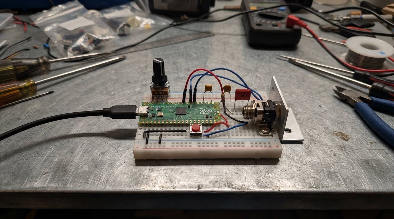
This project turns a Raspberry Pi Pico into a USB MIDI controller with eight buttons and three potentiometer knobs housed in a 3D-printed enclosure. The controller sends MIDI note and control change messages over USB, making it suitable for triggering sounds in DAWs, music production software, or hardware synthesizers.
The guide includes a complete wiring diagram, parts list, firmware code, and step-by-step assembly instructions. Builders will learn how to wire buttons and potentiometers to the Pico's GPIO pins, configure USB MIDI communication, and assemble the printed case with mounted controls and an auxiliary audio jack.
Wiring diagram

Gather all the parts
Assemble it in 7 steps
1. Create the two printable parts
Open `data/pico_midi_controller_case.scad` in OpenSCAD. Set `part` to `"bottom"`, render it, and export it as `pico_midi_controller_bottom.stl`. Then set `part` to `"lid"`, render it, and export it as `pico_midi_controller_lid.stl`. The model makes a 150 mm wide, 95 mm deep desktop case with a rear opening for the Pico USB cable and a small front-right hole for the aux socket.
- Print both parts in PLA or PETG at 0.2 mm layers with about 20% infill.
- The file is editable: hole positions and diameters are collected near the top if your physical controls differ slightly.
- Smooth any sharp plastic around the rear USB opening so it cannot cut into the cable.
2. Check the printed holes before installing everything
Place one 12 mm button in a button hole, one potentiometer in a knob hole, and the 3.5 mm aux jack in the small front-right hole before fitting the rest. The model uses 12.4 mm button holes, 7.4 mm potentiometer shaft holes, and a 6.5 mm jack hole.
- If a hole is tight, carefully widen it a little at a time with a hand reamer or round file.
- The knobs go in the row nearest the back; the buttons fill two rows below them.
- Do not force a control into an undersized hole; this can crack the printed lid or damage its threads.
3. Mount the controls and aux socket in the lid
Fit knob 1, knob 2, and knob 3 from left to right into the three upper holes and tighten their front nuts. Fit button 1 through button 4 from left to right in the first button row, then button 5 through button 8 from left to right in the second row. Fit the 3.5 mm aux jack in the small front-right hole and tighten its nut. Tighten each retaining nut only enough to stop the part turning.
- Keep all button terminals facing the same direction to make the inside wiring tidy.
- Add labels after you have tested which MIDI note or control each part sends.
- Keep bare terminals from touching each other; touching terminals can make a button behave as though it is always pressed.
4. Place the Pico in the base
Put the Raspberry Pi Pico inside the bottom tray with its USB connector facing the rear slot. The two raised rails hold the board in position. Add a small piece of foam tape beneath the Pico if it can move when the case is shaken.
- Test that a USB plug slides straight through the rear slot before wiring the controls.
- Leave enough loose wire near the USB end that the cable does not bend the Pico.
- Do not let the underside of the Pico touch loose nuts, screws, or bare wire ends; this can short the board when USB power is connected.
5. Wire the buttons and knobs
With the Pico unplugged, connect button 1 through button 8 as follows: each button GND terminal → any Pico GND pin (ground); button 1 signal → GPIO6 (signal), button 2 signal → GPIO7 (signal), button 3 signal → GPIO8 (signal), button 4 signal → GPIO9 (signal), button 5 signal → GPIO10 (signal), button 6 signal → GPIO11 (signal), button 7 signal → GPIO12 (signal), and button 8 signal → GPIO13 (signal). For each knob, connect one outer leg → Pico 3V3 (power), the other outer leg → Pico GND (ground), and its middle leg → GPIO26 for knob 1, GPIO27 for knob 2, or GPIO28 for knob 3 (signal).
- Use black wire for ground, red wire for 3V3, and different colors for signal wires.
- If a knob turns backwards, swap its two outer wires; leave its middle wire on the same GPIO.
- Use Pico 3V3 for every knob, never 5V — putting 5V into GPIO26, GPIO27, or GPIO28 can damage the Pico.
6. Wire the aux sound output
Connect Pico GPIO14 → one end of the 1 kΩ resistor (sound signal). Connect the resistor’s other end → 10 nF capacitor P1 and → 1 µF non-polar capacitor P1 (filtered sound junction). Connect 10 nF capacitor P2 → Pico GND (noise filter ground). Connect 1 µF capacitor P2 → aux jack TIP and → aux jack RING (sound to both earphone channels). Connect aux jack SLEEVE → Pico GND (ground).
- Keep the resistor and both capacitors close to the aux jack, then cover their bare legs with heat-shrink tube or electrical tape.
- This jack is a low-power line output: plug it into powered computer speakers, a portable speaker with an AUX input, or an amplifier.
- Do not connect headphones or an unpowered speaker directly to this jack; it is not strong enough to drive them safely or loudly.
- The controller still needs 5V USB power from a phone charger, power bank, or computer. The aux jack supplies sound, not power.
7. Close the printed case
Tuck the wires below the lid so none cross the rim, place the lid on the base, and check that it sits flat. The lid has an inner skirt that locates it in the base. Use a small piece of tape on the inside seam or add four small self-tapping screws through the side walls if you want the case permanently closed.
- Before closing it fully, turn each knob and press each button to make sure no wire is snagging.
- Use a USB data cable for MIDI with a computer; a normal USB power source is enough for standalone aux sound.
- Do not pinch a wire between the lid and base; pinched insulation can later cause a short circuit.
Review all connections
1. Connections between "button_1" and "Raspberry Pi Pico"
2. Connections between "button_2" and "Raspberry Pi Pico"
3. Connections between "button_3" and "Raspberry Pi Pico"
4. Connections between "button_4" and "Raspberry Pi Pico"
5. Connections between "button_5" and "Raspberry Pi Pico"
6. Connections between "button_6" and "Raspberry Pi Pico"
7. Connections between "button_7" and "Raspberry Pi Pico"
8. Connections between "button_8" and "Raspberry Pi Pico"
9. Connections between "knob_1" and "Raspberry Pi Pico"
10. Connections between "knob_2" and "Raspberry Pi Pico"
11. Connections between "knob_3" and "Raspberry Pi Pico"
12. Connections between "audio_resistor" and "Raspberry Pi Pico"
13. Connections between "audio_filter_cap" and "Raspberry Pi Pico"
14. Connections between "audio_coupling_cap" and "Raspberry Pi Pico"
15. Connections between "aux_jack" and "Raspberry Pi Pico"
Deploy the firmware
#include <Arduino.h>
// Use only the MIDI device header.  The all-in-one Adafruit header also pulls
// in USB mass-storage and SD-card code, which this controller does not use.
#include <Adafruit_USBD_MIDI.h>

// Physical wiring pins

// Forward declarations
void sendMidiMessage(uint8_t status, uint8_t data1, uint8_t data2);
void updateAuxTone();

constexpr uint8_t BUTTON_1_PIN = 6;
constexpr uint8_t BUTTON_2_PIN = 7;
constexpr uint8_t BUTTON_3_PIN = 8;
constexpr uint8_t BUTTON_4_PIN = 9;
constexpr uint8_t BUTTON_5_PIN = 10;
constexpr uint8_t BUTTON_6_PIN = 11;
constexpr uint8_t BUTTON_7_PIN = 12;
constexpr uint8_t BUTTON_8_PIN = 13;
constexpr uint8_t KNOB_1_PIN = 26;
constexpr uint8_t KNOB_2_PIN = 27;
constexpr uint8_t KNOB_3_PIN = 28;
constexpr uint8_t AUX_AUDIO_PIN = 14;

constexpr uint8_t BUTTON_COUNT = 8;
constexpr uint8_t KNOB_COUNT = 3;
constexpr uint8_t MIDI_CHANNEL = 0;  // MIDI channel 1 is zero in code.
constexpr uint32_t DEBOUNCE_MS = 20;
constexpr uint8_t KNOB_DEADBAND = 2;

// The browser simulator has no USB-device stack. This guard changes only its build;
// a real Pico still creates the USB MIDI interface.
#if defined(ARDUINO_ARCH_RP2040)
Adafruit_USBD_MIDI usbMidi;
#endif

const uint8_t buttonPins[BUTTON_COUNT] = {
  BUTTON_1_PIN, BUTTON_2_PIN, BUTTON_3_PIN, BUTTON_4_PIN,
  BUTTON_5_PIN, BUTTON_6_PIN, BUTTON_7_PIN, BUTTON_8_PIN
};

const uint8_t knobPins[KNOB_COUNT] = {KNOB_1_PIN, KNOB_2_PIN, KNOB_3_PIN};
const uint8_t noteNumbers[BUTTON_COUNT] = {60, 61, 62, 63, 64, 65, 66, 67};
const uint8_t controllerNumbers[KNOB_COUNT] = {20, 21, 22};
const uint16_t noteFrequencies[BUTTON_COUNT] = {262, 277, 294, 311, 330, 349, 370, 392};

bool buttonPressed[BUTTON_COUNT];
bool lastRawPressed[BUTTON_COUNT];
uint32_t lastEdgeMs[BUTTON_COUNT];
int lastKnobValue[KNOB_COUNT] = {-1, -1, -1};

void sendMidiMessage(uint8_t status, uint8_t data1, uint8_t data2) {
  // A USB cable connected only to a charger still powers the audio preview.
  // MIDI is sent only after a computer has finished recognizing the controller.
#if defined(ARDUINO_ARCH_RP2040)
  if (!TinyUSBDevice.mounted()) {
    return;
  }

  uint8_t message[3] = {status, data1, data2};
  tud_midi_stream_write(0, message, sizeof(message));
#else
  (void)status;
  (void)data1;
  (void)data2;
#endif
}

void updateAuxTone() {
  // The first currently held button supplies the one-voice audio preview.
  for (uint8_t i = 0; i < BUTTON_COUNT; ++i) {
    if (buttonPressed[i]) {
      tone(AUX_AUDIO_PIN, noteFrequencies[i]);
      return;
    }
  }
  noTone(AUX_AUDIO_PIN);
}

void setup() {
  analogReadResolution(10);
  pinMode(AUX_AUDIO_PIN, OUTPUT);
  noTone(AUX_AUDIO_PIN);

  for (uint8_t i = 0; i < BUTTON_COUNT; ++i) {
    pinMode(buttonPins[i], INPUT_PULLUP);
    bool pressed = digitalRead(buttonPins[i]) == LOW;
    buttonPressed[i] = pressed;
    lastRawPressed[i] = pressed;
    lastEdgeMs[i] = millis();
  }

#if defined(ARDUINO_ARCH_RP2040)
  usbMidi.setStringDescriptor("Pico MIDI Controller");
  usbMidi.begin();
  TinyUSBDevice.begin(0);
#endif
}

void loop() {
  const uint32_t now = millis();

  for (uint8_t i = 0; i < BUTTON_COUNT; ++i) {
    const bool rawPressed = digitalRead(buttonPins[i]) == LOW;

    if (rawPressed != lastRawPressed[i]) {
      lastRawPressed[i] = rawPressed;
      lastEdgeMs[i] = now;
    }

    if (rawPressed != buttonPressed[i] && now - lastEdgeMs[i] >= DEBOUNCE_MS) {
      buttonPressed[i] = rawPressed;
      const uint8_t status = buttonPressed[i] ? 0x90 : 0x80;
      const uint8_t velocity = buttonPressed[i] ? 127 : 0;
      sendMidiMessage(status | MIDI_CHANNEL, noteNumbers[i], velocity);
      updateAuxTone();
    }
  }

  for (uint8_t i = 0; i < KNOB_COUNT; ++i) {
    const int midiValue = map(analogRead(knobPins[i]), 0, 1023, 0, 127);
    if (lastKnobValue[i] < 0 || abs(midiValue - lastKnobValue[i]) >= KNOB_DEADBAND) {
      lastKnobValue[i] = midiValue;
      sendMidiMessage(0xB0 | MIDI_CHANNEL, controllerNumbers[i], midiValue);
    }
  }

  delay(2);
}
Download project files
Remix this project
Make it yours in one click
Open a full copy of this project in your own Schematik workspace — diagram, code, parts, and assembly steps included. Swap the sensor, add features, or redesign the whole thing with AI. The author's original stays untouched.
Related projects
Drone Light Safety Controller (copy)
Raspberry Pi Pico · September 26, 2026ianlex.wip
RGB Button Color Controller
Raspberry Pi Pico · September 25, 2026juliaccquintanilha
Zaprojektuj Emulator Rom Dla Zx Spectrum Harlequ
Raspberry Pi Pico · September 25, 2026Piotr Chmielecki