Community project
AI Companion Head
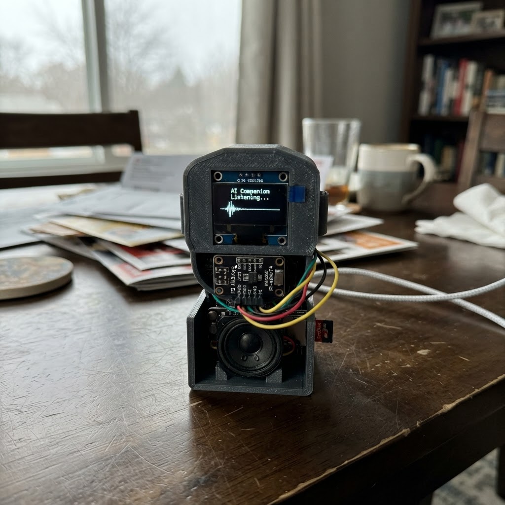
Build an AI Companion Head that displays animated faces on an OLED screen and responds with synthesized speech through a speaker. This ESP32-based project receives commands from a PC over Wi-Fi, allowing the companion to show expressions and play audio generated by an AI model running on the host computer.
The guide provides a complete wiring diagram connecting the SSD1306 display, INMP441 microphone, MAX98357A amplifier, speaker, and MicroSD card module to the ESP32. Assembly steps cover safe wiring practices, firmware configuration for Wi-Fi and audio settings, and customization of facial animations through the provided C++ code.
Wiring diagram

Gather all the parts
Assemble it in 6 steps
1. Keep USB disconnected while wiring
Build the circuit on a breadboard or secure wiring harness first. Use the ESP32 USB port as the only power source for this version.
- Use short wires for I²S audio connections to reduce noise.
- All modules must share ESP32 GND.
- Do not power the INMP441 microphone from 5 V.
- Do not connect either speaker terminal to GND; the MAX98357A speaker outputs are a paired amplifier output.
2. Wire the OLED screen
Connect OLED VCC to ESP32 3V3 and OLED GND to ESP32 GND. Connect OLED SDA to GPIO21 and OLED SCL to GPIO22.
- This assumes the selected 128×64 I²C SSD1306 OLED with address 0x3C.
- If the screen remains blank, confirm its VCC/GND labels and I²C address before changing any wiring.
- Use 3.3 V for the OLED to keep its I²C signals safe for the ESP32.
3. Wire the I²S microphone
Connect INMP441 VDD to 3V3, GND to GND, and L/R to GND (left channel). Connect SCK to GPIO32, WS to GPIO33, and SD to GPIO16.
- Place the microphone away from the speaker so it is less likely to hear its own reply audio.
- INMP441 VDD must be 3.3 V maximum.
4. Wire amplifier and speaker
Connect MAX98357A VIN to ESP32 5V/VIN, and GND to ESP32 GND. Connect BCLK to GPIO26, LRC to GPIO25, and DIN to GPIO27. Connect amplifier SPK+ to speaker POS and amplifier SPK- to speaker NEG.
- The amplifier is supplied from USB's 5 V rail for useful speaker volume.
- Keep the two speaker leads together and separate from microphone wires where possible.
- Never connect SPK+ or SPK- to the ESP32, 5 V, or GND.
- Start with a 1 W or higher 8 Ω speaker.
5. Wire the microSD adapter
Connect SD adapter VCC to 3V3 and GND to GND. Connect MISO to GPIO19, MOSI to GPIO23, SCK to GPIO18, and CS to GPIO4. Insert a FAT32-formatted microSD card after wiring.
- Use an adapter designed for 3.3 V SPI logic, or one explicitly marked safe with 3.3 V ESP32 signals.
- Do not use a 5 V-only SD module with 3.3 V ESP32 signal pins.
6. Power the body and connect the PC
Connect USB power and use Schematik’s Deploy button. The ESP32 creates Wi-Fi named Companion-Body. Connect the PC running the companion program to that network, then let the PC send display-state, text, and audio commands to the ESP32 at 192.168.4.1.
- The network password and other body settings are in src/companion_settings.h.
- The PC program is the brain: it performs AI, speech recognition, text-to-speech, and decides what the OLED shows.
- Change the default Wi-Fi password in companion_settings.h before regular use.
- This SSD1306 screen is monochrome. The PC can select face animations and text, but it cannot mirror a colour picture or normal GIF exactly.
Review all connections
1. Connections between "oled_1" and "ESP32"
2. Connections between "mic_1" and "ESP32"
3. Connections between "amp_1" and "ESP32"
4. Connections between "sd_1" and "ESP32"
Deploy the firmware
// PC Mirror Companion — ESP32 body firmware
// GENERATE: the PC's AI sends state/text/audio commands below.
// MODIFY: edit face and animation drawing in companion_body.cpp.
// SETTINGS: edit Wi-Fi and audio values in companion_settings.h.
#include <Arduino.h>
#include <WiFi.h>
#include <WebServer.h>
#include "driver/i2s.h"
#include "companion_settings.h"
#include "companion_body.h"


// Forward declarations
void startSpeaker();
void sendJson(const String &json);
void handleStatus();
void handleSet();
void handleSpeak();
void handleRoot();

constexpr int AMP_BCLK = 26;
constexpr int AMP_LRCLK = 25;
constexpr int AMP_DIN = 27;
WebServer server(BODY_HTTP_PORT);

void startSpeaker() {
  i2s_config_t config = {};
  config.mode = (i2s_mode_t)(I2S_MODE_MASTER | I2S_MODE_TX);
  config.sample_rate = PCM_SAMPLE_RATE;
  config.bits_per_sample = I2S_BITS_PER_SAMPLE_16BIT;
  config.channel_format = I2S_CHANNEL_FMT_RIGHT_LEFT;
  config.communication_format = I2S_COMM_FORMAT_I2S;
  config.intr_alloc_flags = ESP_INTR_FLAG_LEVEL1;
  config.dma_buf_count = 4;
  config.dma_buf_len = 128;
  config.tx_desc_auto_clear = true;
  i2s_driver_install(I2S_NUM_1, &config, 0, nullptr);
  i2s_pin_config_t pins = {};
  pins.bck_io_num = AMP_BCLK;
  pins.ws_io_num = AMP_LRCLK;
  pins.data_out_num = AMP_DIN;
  pins.data_in_num = I2S_PIN_NO_CHANGE;
  i2s_set_pin(I2S_NUM_1, &pins);
  i2s_zero_dma_buffer(I2S_NUM_1);
}

void sendJson(const String &json) {
  server.sendHeader("Access-Control-Allow-Origin", "*");
  server.send(200, "application/json", json);
}
void handleStatus() {
  String json = "{\"state\":\"" + bodyStateName() + "\",\"text\":\"" + bodyText() +
                "\",\"ip\":\"" + WiFi.softAPIP().toString() + "\"}";
  sendJson(json);
}
void handleSet() {
  if (!server.hasArg("state") && !server.hasArg("text")) {
    server.send(400, "text/plain", "Use state and/or text query values.");
    return;
  }
  if (server.hasArg("state")) bodySetState(server.arg("state"));
  if (server.hasArg("text")) bodySetText(server.arg("text"));
  if (server.hasArg("contrast")) bodySetContrast((uint8_t)constrain(server.arg("contrast").toInt(), 0, 255));
  handleStatus();
}
void handleSpeak() {
  // PC TTS sends raw signed 16-bit, 16 kHz, mono PCM in the POST body.
  if (server.method() != HTTP_POST) {
    server.send(405, "text/plain", "POST raw 16-bit mono PCM data.");
    return;
  }
  bodySetState("talking");
  const String &raw = server.arg("plain");
  const uint8_t *bytes = (const uint8_t *)raw.c_str();
  for (size_t offset = 0; offset + 1 < raw.length(); offset += 2) {
    int16_t sample = (int16_t)((uint16_t)bytes[offset] | ((uint16_t)bytes[offset + 1] << 8));
    int16_t stereo[2] = {sample, sample};
    size_t written;
    i2s_write(I2S_NUM_1, stereo, sizeof(stereo), &written, portMAX_DELAY);
  }
  bodySetState("idle");
  sendJson("{\"ok\":true}");
}
void handleRoot() {
  server.send(200, "text/html", "<h2>PC Mirror Companion</h2><p>PC control endpoint ready.</p><p>GET /set?state=listening&text=Hello</p><p>GET /status</p>");
}

void setup() {
  Serial.begin(115200);
  bodyBegin();
  startSpeaker();
  WiFi.mode(WIFI_AP);
  WiFi.softAP(BODY_AP_NAME, BODY_AP_PASSWORD);
  bodySetText("Connect PC to Wi-Fi");
  server.on("/", HTTP_GET, handleRoot);
  server.on("/status", HTTP_GET, handleStatus);
  server.on("/set", HTTP_GET, handleSet);
  server.on("/speak", HTTP_POST, handleSpeak);
  server.begin();
}
void loop() {
  server.handleClient();
  bodyTick();
}
Remix this project
Make it yours in one click
Open a full copy of this project in your own Schematik workspace — diagram, code, parts, and assembly steps included. Swap the sensor, add features, or redesign the whole thing with AI. The author's original stays untouched.
Related projects

Create A Complete Electrical Schematic Esp32 Sma
ESP32 · September 17, 2026Ayansh Agrawal
ESP32 Kare Ekran Projeleri
ESP32 · September 16, 2026Seref Ai
Component Qty --------------------------- ------
ESP32 · September 16, 2026Yathartha Chakrawal