Community project
Portable GPS Tracker
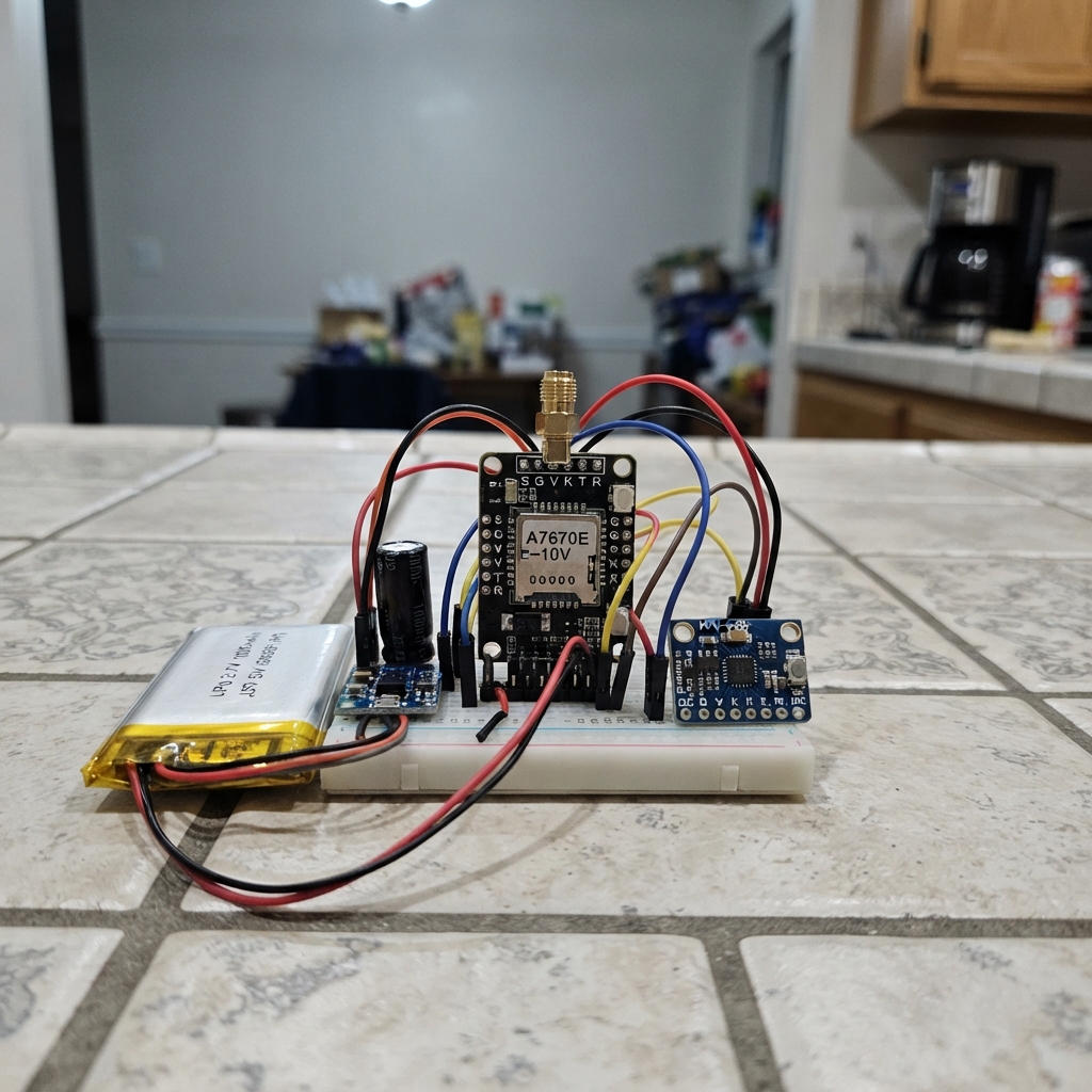
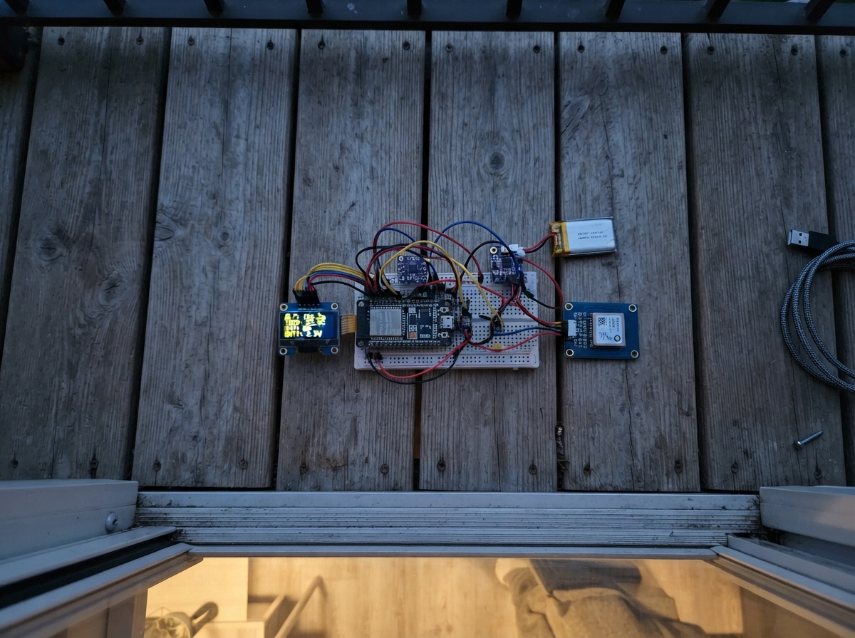
This portable GPS tracker uses an ESP32 microcontroller paired with an A7670E LTE modem to capture and transmit location data. The device combines a 3.7V LiPo battery with a Pololu boost regulator to reliably power the modem, while an MPU-6050 accelerometer tracks motion. The guide provides a complete wiring diagram, parts list, and step-by-step assembly instructions to build a compact tracker capable of determining GPS fixes and reporting coordinates over cellular.
The firmware handles NMEA sentence parsing to extract latitude and longitude from GPS data, validates checksums, and manages modem communication over a hardware serial connection. Builders will learn how to configure the destination phone number via USB serial, integrate power management with a Schottky diode and capacitor, and test the tracker outdoors to verify GPS acquisition and cellular connectivity.
Wiring diagram
Gather all the parts
Assemble it in 6 steps
1. Check battery and modem before wiring
Use a protected 3.7V 1000mAh LiPo rated for at least 5A discharge, including its protection circuit. Confirm your modem has the 5–10V S G V K T R G header, not a bare-module VBAT supply. Fit its LTE antenna and an active SIM with SMS service and no PIN lock before powering it.
- A low-current LiPo may shut down or overheat during modem bursts. Never attach a LiPo directly to the modem V pin.
2. Build the power supply
With battery disconnected, connect battery positive to boost VIN and negative to boost GND. Connect boost GND to XIAO GND. Boost VOUT goes to modem V. Modem G goes to GND. Use the compact Pololu U3V40F5 (item 4012), 15.2 x 15.2 x 5.6 mm. Leave boost EN open. Solder short thick wires directly to the labeled pads instead of fitting tall headers; VIN and GND each have duplicated pads. Do not use breadboard power rails.
3. Isolate USB and steady modem power
Connect diode A to boost VOUT and its striped K end to XIAO 5V. Put capacitor positive at modem V and striped negative at GND, close to the modem. Leave XIAO battery pads unused.
- Reversing the electrolytic capacitor can make it burst. Never connect modem USB while the boost supply is powering it.
4. Connect modem and motion sensor data
Remove the separate GP-02 and its wires. Modem T goes to XIAO D4 (GPIO6) for replies and GPS data; modem R goes to D5 (GPIO7) for commands. Leave S and K open. GY-521 VCC goes to XIAO 3V3, GND to GND, SDA to D2 (GPIO4, data), SCL to D3 (GPIO5, clock), and AD0 to GND. Leave INT, XDA and XCL open. Do not power GY-521 from 5V because its pull-ups could expose XIAO to 5V. Its onboard pull-ups are used. Serial output shows acceleration and rotation once per second; it does not change SMS timing or implement motion wake-up.
5. Inspect and test outdoors
Check polarity and verify boost output is 5V with a meter before connecting the modules. Connect battery last. Test several cold starts and SMS sends with a partly discharged battery before enclosing it; the 1000uF output capacitor and modem load can stress regulator startup. If output fails to reach 5V or the modem resets, disconnect power and resolve it before use. Keep the regulator ventilated and away from the LiPo pouch; it can get hot. Insulate exposed joints without crushing the battery. Position the GPS antenna facing open sky and away from the cellular antenna. Allow several minutes for the first location fix. This modem breakout starts with K left alone. Firmware waits 20 seconds then enables GPS on the shared UART, retrying on errors. Set DEFAULT_PHONE in the firmware or send PHONE +countrycodeNumber through USB serial. SEND requests a map link; automatic SMS remains every five minutes with a fresh fix.
- The modem needs up to 2A at 5V in bursts. Runtime is roughly 2 hours and varies strongly with coverage. This version stays awake; it is not a multi-day tracker.
6. Charge separately
Unplug the battery from the tracker and charge it using a compatible single-cell 4.2V LiPo charger at no more than 500mA unless its manufacturer specifies a lower limit. USB on the XIAO does not charge the battery in this wiring. Insulate all joints and secure the battery without crushing it.
Review all connections
1. Connections between "battery" and "ESP32"
2. Connections between "boost" and "ESP32"
3. Connections between "modem" and "ESP32"
4. Connections between "diode" and "ESP32"
5. Connections between "capacitor" and "ESP32"
6. Connections between "imu" and "ESP32"
Deploy the firmware
#include <Arduino.h>
#include <Preferences.h>
#include <Wire.h>
// Set your destination here, or type PHONE +countrycodeNumber in USB serial.
const char *DEFAULT_PHONE = "";
constexpr int MODEM_RX = 6, MODEM_TX = 7;
HardwareSerial modem(1);
Preferences prefs;
String phone, nmea, usb;
double latitude=0, longitude=0;
bool fix=false;
uint32_t fixTime=0, lastAttempt=0;
void pumpGPS();
String field(const String &s, int index) {
  int start=0;
  while(index--) { start=s.indexOf(',',start); if(start<0) return ""; ++start; }
  int end=s.indexOf(',',start); if(end<0) end=s.indexOf('*',start);
  return s.substring(start,end<0?s.length():end);
}
double coordinateDegrees(String value) {
  double v=value.toDouble(); int deg=int(v/100); return deg+(v-deg*100)/60.0;
}
void parse(const String &s) {
  int star=s.indexOf('*'); if(star<0 || star+2>=int(s.length())) return;
  uint8_t sum=0; for(int i=1;i<star;i++) sum^=s[i];
  if(sum!=strtoul(s.substring(star+1,star+3).c_str(),nullptr,16)) return;
  if(s.substring(3,6)!="RMC") return;
  if(field(s,2)!="A") {fix=false; return;}
  String a=field(s,3), b=field(s,5); if(a.isEmpty()||b.isEmpty()) return;
  latitude=coordinateDegrees(a)*(field(s,4)=="S"?-1:1);
  longitude=coordinateDegrees(b)*(field(s,6)=="W"?-1:1);
  fix=true; fixTime=millis();
}
// NMEA and AT responses share the modem UART. Feed every byte to both parsers.
void gpsByte(char c) {
  if(c=='$') nmea="";
  if(c=='\n') { if(nmea.startsWith("$")) parse(nmea); nmea=""; }
  else if(c!='\r' && nmea.length()<150) nmea+=c;
}
void pumpGPS() {
  while(modem.available()) { char c=modem.read(); gpsByte(c); }
}
bool imuOK=false;
float ax,ay,az,gx,gy,gz;
bool imuWrite(uint8_t reg,uint8_t value) {
  Wire.beginTransmission(0x68); Wire.write(reg); Wire.write(value);
  return Wire.endTransmission()==0;
}
bool imuRead(uint8_t reg,uint8_t *data,uint8_t count) {
  Wire.beginTransmission(0x68); Wire.write(reg);
  if(Wire.endTransmission(false)!=0) return false;
  if(Wire.requestFrom(uint8_t(0x68),count)!=count) return false;
  for(int i=0;i<count;i++) data[i]=Wire.read();
  return true;
}
void sampleIMU() {
  uint8_t b[14]; if(!imuOK || !imuRead(0x3B,b,14)) return;
  auto word=[&](int i) {return int16_t((uint16_t(b[i])<<8)|b[i+1]);};
  ax=word(0)/16384.0f; ay=word(2)/16384.0f; az=word(4)/16384.0f;
  gx=word(8)/131.0f; gy=word(10)/131.0f; gz=word(12)/131.0f;
  Serial.printf("Accel g: %.2f %.2f %.2f | Gyro deg/s: %.1f %.1f %.1f\n",ax,ay,az,gx,gy,gz);
}
bool waitFor(const char *token, uint32_t timeout) {
  String reply; uint32_t start=millis();
  while(millis()-start<timeout) {
    while(modem.available()) {
      char c=modem.read(); gpsByte(c); reply+=c;
      if(reply.indexOf(token)>=0) return true;
      if(reply.indexOf("ERROR")>=0) return false;
      if(reply.length()>1000) reply.remove(0,500);
    }
    delay(1);
  }
  return false;
}
bool command(const String &s, uint32_t timeout=3000) {
  pumpGPS();
  modem.println(s); return waitFor("OK",timeout);
}
bool validPhone(const String &s) {
  if(s.length()<8 || s.length()>16 || s[0]!='+') return false;
  for(unsigned i=1;i<s.length();i++) if(!isDigit(s[i])) return false;
  return true;
}
void sendLocation() {
  if(!validPhone(phone)) {Serial.println("Set destination: PHONE +countrycodeNumber");return;}
  if(!fix || millis()-fixTime>15000) {Serial.println("No fresh GPS fix. Move outdoors.");return;}
  if(!command("AT") || !command("AT+CMGF=1")) return;
  modem.println("AT+CMGS=\""+phone+"\"");
  if(!waitFor(">",5000)) return;
  modem.print("Location: https://maps.google.com/?q=");
  modem.print(latitude,6); modem.print(','); modem.print(longitude,6);
  modem.write(26);
  if(waitFor("OK",60000)) Serial.println("SMS accepted by modem.");
  else Serial.println("SMS failed/timed out. Check SIM, coverage and supply.");
}
void setup() {
  Serial.begin(115200);
  Wire.begin(4,5); Wire.setTimeOut(50);
  uint8_t who=0;
  imuOK=imuRead(0x75,&who,1) && who==0x68;
  if(imuOK) imuOK=imuWrite(0x6B,1) && imuWrite(0x1B,0) && imuWrite(0x1C,0) && imuWrite(0x1A,3);
  Serial.println(imuOK?"MPU6050 ready":"MPU6050 not found: check wiring and 3.3V supply");
  modem.setRxBufferSize(4096);
  modem.begin(115200,SERIAL_8N1,MODEM_RX,MODEM_TX);
  prefs.begin("tracker",false); phone=prefs.getString("phone",DEFAULT_PHONE);
  Serial.println("GPS tracker: PHONE +number stores recipient; SEND sends now. Automatic interval: 5 minutes.");
  lastAttempt=millis()-300000UL;
}
void loop() {
  static bool ready=false;
  static uint32_t initAttempt=0, imuTime=0;
  pumpGPS();
  if(!ready && millis()>20000 && millis()-initAttempt>10000) {
    initAttempt=millis();
    ready=command("AT") && command("ATE0") && command("AT+CGNSSPWR=1",10000)
      && command("AT+CGNSSTST=1") && command("AT+CGNSSPORTSWITCH=0,1");
    Serial.println(ready?"Modem GPS enabled; waiting for outdoor fix":"Modem GPS init failed; will retry");
  }
  if(millis()-imuTime>=1000) {imuTime=millis();sampleIMU();}
  while(Serial.available()) {
    char c=Serial.read();
    if(c=='\n') {
      usb.trim();
      if(usb.startsWith("PHONE ")) {
        String p=usb.substring(6); p.trim();
        if(validPhone(p)) { phone=p; prefs.putString("phone",phone); Serial.println("Recipient saved."); }
        else Serial.println("Use + followed by country code and digits.");
      } else if(usb=="SEND") sendLocation();
      usb="";
    } else if(usb.length()<80) usb+=c;
  }
  if(validPhone(phone) && fix && millis()-fixTime<15000 && millis()-lastAttempt>=300000UL) {
    lastAttempt=millis(); sendLocation();
  }
  pumpGPS();
  delay(1);
}
Remix this project
Make it yours in one click
Open a full copy of this project in your own Schematik workspace, diagram, code, parts, and assembly steps included. Swap the sensor, add features, or redesign the whole thing with AI. The author's original stays untouched.