Community project
Bluetooth Joystick Gamepad
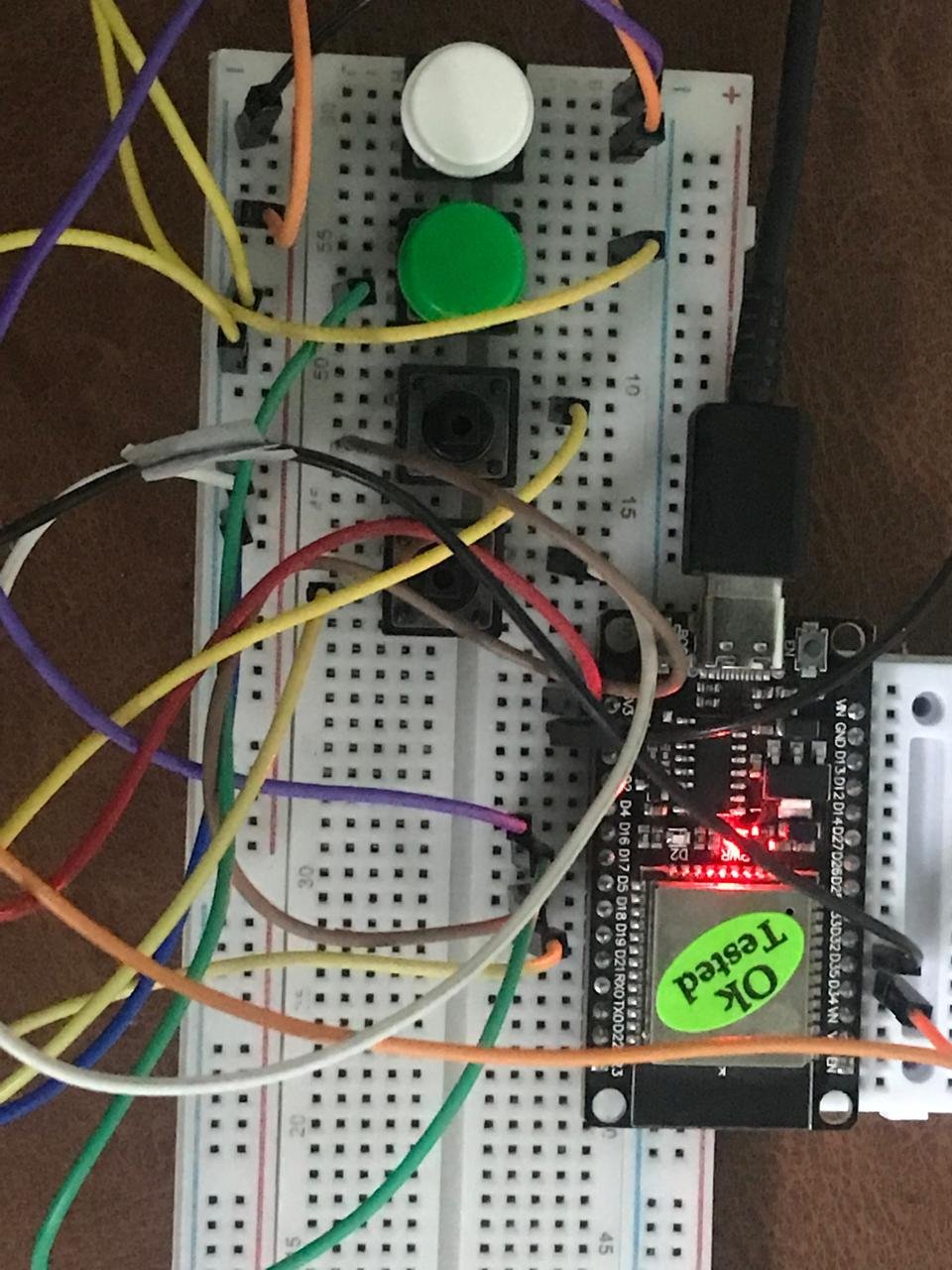
Build a wireless gamepad controller using an ESP32 microcontroller and a PS2 joystick module. This project combines analog stick input with four push buttons to create a Bluetooth gamepad that connects to computers, phones, and gaming devices without any wired connection.
This guide provides a complete wiring diagram, parts list, and step-by-step assembly instructions to get the gamepad working. The included firmware handles joystick calibration, dead zone filtering, and Bluetooth HID communication, so the controller appears as a standard gamepad to any connected device.
Wiring diagram
Gather all the parts
Assemble it in 6 steps
1. Place the controller parts
Put the ESP32 DevKit V1, the small joystick board, and four push buttons on a breadboard or panel. Label the buttons A, B, X, and Y so their on-screen names match the wires.
- Keep the ESP32 USB socket reachable so you can plug in its USB cable later.
2. Power the joystick safely
Run one red wire from the ESP32 3V3 pin to the joystick pin marked +5V or VCC, and one black wire from ESP32 GND to joystick GND. The label says +5V on many joystick boards, but 3.3 V is correct here and protects the ESP32 input pins.
- Do not connect the joystick power pin to the ESP32 5V/VIN pin; then its axis signals can reach 5 V and damage the ESP32.
3. Connect the joystick directions
Connect joystick VRX to GPIO34 (left/right signal) and joystick VRY to GPIO35 (up/down signal). Leave the joystick SW pin empty; this simple version uses the separate four buttons instead.
- GPIO34 and GPIO35 are the pins labeled 34 and 35 on the ESP32 board.
4. Wire the A and B buttons
For each push button, connect one leg to an ESP32 GND pin. Connect the other leg of button A to GPIO16 and the other leg of button B to GPIO17. Each button works by joining its signal wire to ground when pressed.
- On a small four-legged tactile button, use legs on opposite sides of the button; the two legs on the same side are already joined together.
5. Wire the X and Y buttons
For each remaining push button, connect one leg to ESP32 GND. Connect the other leg of button X to GPIO18 and the other leg of button Y to GPIO19.
- All five ground wires may share any GND pin on the ESP32, using a breadboard ground row if that is easier.
6. Check before powering
Check every wire against the labels: joystick VCC to 3V3 (power), joystick GND to GND (ground), VRX to GPIO34 (left/right signal), VRY to GPIO35 (up/down signal), A to GPIO16 (signal), B to GPIO17 (signal), X to GPIO18 (signal), and Y to GPIO19 (signal).
- Make sure the joystick VCC and GND wires are not swapped; swapped power can damage the joystick board or ESP32.
Review all connections
1. Connections between "joystick_1" and "ESP32"
2. Connections between "button_a" and "ESP32"
3. Connections between "button_b" and "ESP32"
4. Connections between "button_x" and "ESP32"
5. Connections between "button_y" and "ESP32"
Deploy the firmware
#include <Arduino.h>
#include <BleGamepad.h>

constexpr int JOY_X_PIN = 34;
constexpr int JOY_Y_PIN = 35;
constexpr int BUTTON_A_PIN = 16;
constexpr int BUTTON_B_PIN = 17;
constexpr int BUTTON_X_PIN = 18;
constexpr int BUTTON_Y_PIN = 19;

constexpr int ADC_MAX = 4095;
constexpr int DEAD_ZONE = 110;
constexpr uint32_t REPORT_INTERVAL_MS = 20;

BleGamepad bleGamepad("ESP32 Simple Gamepad", "Schematik", 100);

int16_t previousX = 0;
int16_t previousY = 0;
bool previousButtons[4] = {false, false, false, false};
uint32_t lastReportMs = 0;

int16_t readAxis(int pin, bool invert) {
  int raw = analogRead(pin);
  int centered = raw - (ADC_MAX / 2);

  if (abs(centered) < DEAD_ZONE) {
    centered = 0;
  }

  long value = map(centered, -(ADC_MAX / 2), ADC_MAX / 2, -32767, 32767);
  value = constrain(value, -32767, 32767);
  return invert ? -value : value;
}

bool readPressed(int pin) {
  return digitalRead(pin) == LOW;
}

void setButton(uint8_t number, bool pressed) {
  if (pressed) {
    bleGamepad.press(number);
  } else {
    bleGamepad.release(number);
  }
}

void setup() {
  pinMode(BUTTON_A_PIN, INPUT_PULLUP);
  pinMode(BUTTON_B_PIN, INPUT_PULLUP);
  pinMode(BUTTON_X_PIN, INPUT_PULLUP);
  pinMode(BUTTON_Y_PIN, INPUT_PULLUP);

  analogReadResolution(12);
  bleGamepad.begin();
}

void loop() {
  const uint32_t now = millis();
  if (now - lastReportMs < REPORT_INTERVAL_MS) {
    delay(REPORT_INTERVAL_MS - (now - lastReportMs));
    return;
  }
  lastReportMs = now;

  const int16_t x = readAxis(JOY_X_PIN, false);
  const int16_t y = readAxis(JOY_Y_PIN, true);
  const bool buttons[4] = {
    readPressed(BUTTON_A_PIN),
    readPressed(BUTTON_B_PIN),
    readPressed(BUTTON_X_PIN),
    readPressed(BUTTON_Y_PIN)
  };

  if (!bleGamepad.isConnected()) {
    delay(1);
    return;
  }

  bool changed = (x != previousX) || (y != previousY);
  for (uint8_t i = 0; i < 4; ++i) {
    if (buttons[i] != previousButtons[i]) {
      changed = true;
    }
  }

  if (!changed) {
    delay(1);
    return;
  }

  bleGamepad.setLeftThumb(x, y);
  for (uint8_t i = 0; i < 4; ++i) {
    setButton(i + 1, buttons[i]);
    previousButtons[i] = buttons[i];
  }
  previousX = x;
  previousY = y;
  bleGamepad.sendReport();
  delay(1);
}
Remix this project
Make it yours in one click
Open a full copy of this project in your own Schematik workspace, diagram, code, parts, and assembly steps included. Swap the sensor, add features, or redesign the whole thing with AI. The author's original stays untouched.