Community project
AI Plant Pest Detector
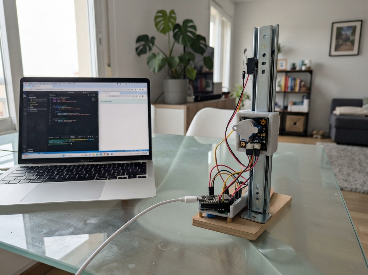
This project builds an automated plant inspection system that scans leaves for pest damage and disease symptoms. The ESP32-CAM captures high-resolution images while a stepper motor moves the camera along a 300 mm rail, and a limit switch ensures repeatable homing. The guide includes a complete wiring diagram, parts list, firmware with leaf-analysis algorithms, and step-by-step assembly instructions for mounting the rail, attaching the motor to the carriage, connecting the limit switch, and performing safe initial tests.
The system analyzes each leaf image for lesion coverage, yellowing, and green area to calculate pest risk scores and alert the user to suspected infestations. Powered by a standard USB-C 5V adapter, the 28BYJ-48 stepper motor module handles motion control while the ESP32 processes vision data in real time.
Wiring diagram

Gather all the parts
Assemble it in 6 steps
1. Monta el riel y la cámara
Atornilla la parte fija de la corredera telescópica de 300 mm a una tabla recta. Sujeta la ESP32-CAM al carro móvil con la lente mirando a las hojas, a unos 10–20 cm de distancia. Mueve el carro a mano de extremo a extremo para comprobar que no roza ni se atasca.
- Deja un bucle suave en los cables de la cámara para que no tiren del carro.
- Una luz uniforme sobre las hojas mejora la detección visual.
- No uses una corredera doblada o floja: las vibraciones hacen que las fotos salgan borrosas.
2. Fija el motor pequeño al carro
Monta el motor 28BYJ-48 con su módulo controlador de 5 V junto al extremo de la corredera y une su eje al carro usando una pequeña pieza de cartón rígido, madera fina o una pieza impresa. Ajusta la unión para que el motor empuje y tire del carro sin forzar los topes del riel.
- Primero prueba el movimiento con la cámara desmontada; después añade la cámara.
- El motor es para un carro ligero: mantén el soporte y los cables lo más livianos posible.
- Mantén dedos, pelo y cables lejos del eje mientras el motor se mueve.
3. Coloca el interruptor de inicio
Atornilla el final de carrera en el extremo de inicio. El carro debe presionar la palanca antes de llegar al tope físico del riel. Conecta COM → GND (tierra) y NO → GPIO13 (señal).
- Presiona la palanca a mano: debe volver a su posición al soltarla.
- No montes el interruptor después del tope del riel: el carro podría chocar antes de poder detenerse.
4. Conecta el módulo del motor
Conecta 5V → 5V (alimentación), GND → GND (tierra), STEP → GPIO14 (pasos) y DIR → GPIO15 (sentido) entre el módulo del motor y la ESP32-CAM. Conecta el motor 28BYJ-48 a su conector blanco del módulo.
- Sujeta los cables al carro con cinta o bridas dejando holgura para todo el recorrido.
- No fuerces el conector blanco del motor: entra en una sola orientación.
5. Alimenta con USB de 5 V
Conecta +5V del adaptador USB → carril de 5 V (alimentación) y GND → carril GND (tierra). Desde esos mismos carriles alimenta la ESP32-CAM y el módulo del motor. Todos los cables GND deben quedar unidos.
- Usa un cargador USB de 5 V capaz de entregar al menos 1 A.
- Antes de enchufar, revisa que el cable de 5 V no toque ningún GPIO.
- No conectes 5 V a un GPIO de la ESP32-CAM: puede dañar la placa.
6. Haz la primera prueba segura
Coloca el carro unos centímetros separado del interruptor de inicio. Conecta la ESP32-CAM por USB, pulsa Deploy y observa el primer recorrido. La cámara buscará el interruptor, revisará cinco puntos y volverá al inicio.
- Si avanza en la dirección equivocada, desconecta la alimentación y cambia la orientación mecánica del motor o invierte el ajuste de sentido en el programa.
- Si no cubre toda la corredera, ajusta después el valor TOTAL_TRAVEL_STEPS de forma gradual.
- Corta la alimentación si el carro intenta seguir moviéndose contra un tope.
Review all connections
1. Connections between "usb_power" and "ESP32"
2. Connections between "school_stepper" and "ESP32"
3. Connections between "home_switch" and "ESP32"
Deploy the firmware
#include <Arduino.h>
#include "esp_camera.h"
#include <math.h>

// Cámara OV2640 integrada de la AI Thinker ESP32-CAM.
#define PWDN_GPIO_NUM     32
#define RESET_GPIO_NUM    -1
#define XCLK_GPIO_NUM      0
#define SIOD_GPIO_NUM     26
#define SIOC_GPIO_NUM     27
#define Y9_GPIO_NUM       35
#define Y8_GPIO_NUM       34
#define Y7_GPIO_NUM       39
#define Y6_GPIO_NUM       36
#define Y5_GPIO_NUM       21
#define Y4_GPIO_NUM       19
#define Y3_GPIO_NUM       18
#define Y2_GPIO_NUM        5
#define VSYNC_GPIO_NUM    25
#define HREF_GPIO_NUM     23
#define PCLK_GPIO_NUM     22

struct LeafFeatures {
  float lesionFraction;
  float yellowFraction;
  float greenFraction;
};


// Forward declarations
bool startCamera();
void oneStep();
void moveSteps(long steps, bool awayFromHome);
bool homeCamera();
LeafFeatures measureLeaf(const camera_fb_t *frame);
float pestRiskModel(const LeafFeatures &f);
void showAlert(bool suspected);
void scanLeafAtCurrentPosition(int position);
void scanRail();

constexpr int FLASH_LED_PIN = 4;
constexpr int STEP_PIN = 14;
constexpr int DIR_PIN = 15;
constexpr int HOME_SWITCH_PIN = 13;

// El módulo 28BYJ-48 incluye su propio controlador de 5 V. GPIO14 envía los pasos,
// GPIO15 elige el sentido y GPIO13 lee el final de carrera.
constexpr unsigned int STEP_PULSE_US = 3000; // Velocidad suave para no sacudir la cámara.
constexpr long HOME_MAX_STEPS = 5200;
constexpr long TOTAL_TRAVEL_STEPS = 3600;  // Valor inicial para 300 mm; ajustar solo si el carro no recorre todo el riel.
constexpr int SCAN_POSITIONS = 5;
constexpr unsigned long SCAN_INTERVAL_MS = 60000;

unsigned long lastScanMs = 0;

bool startCamera() {
  camera_config_t config{};
  config.ledc_channel = LEDC_CHANNEL_0;
  config.ledc_timer = LEDC_TIMER_0;
  config.pin_d0 = Y2_GPIO_NUM;
  config.pin_d1 = Y3_GPIO_NUM;
  config.pin_d2 = Y4_GPIO_NUM;
  config.pin_d3 = Y5_GPIO_NUM;
  config.pin_d4 = Y6_GPIO_NUM;
  config.pin_d5 = Y7_GPIO_NUM;
  config.pin_d6 = Y8_GPIO_NUM;
  config.pin_d7 = Y9_GPIO_NUM;
  config.pin_xclk = XCLK_GPIO_NUM;
  config.pin_pclk = PCLK_GPIO_NUM;
  config.pin_vsync = VSYNC_GPIO_NUM;
  config.pin_href = HREF_GPIO_NUM;
  config.pin_sccb_sda = SIOD_GPIO_NUM;
  config.pin_sccb_scl = SIOC_GPIO_NUM;
  config.pin_pwdn = PWDN_GPIO_NUM;
  config.pin_reset = RESET_GPIO_NUM;
  config.xclk_freq_hz = 20000000;
  config.pixel_format = PIXFORMAT_RGB565;
  config.frame_size = FRAMESIZE_QQVGA;
  config.jpeg_quality = 12;
  config.fb_count = 1;
  return esp_camera_init(&config) == ESP_OK;
}

void oneStep() {
  digitalWrite(STEP_PIN, HIGH);
  delayMicroseconds(STEP_PULSE_US);
  digitalWrite(STEP_PIN, LOW);
  delayMicroseconds(STEP_PULSE_US);
}

void moveSteps(long steps, bool awayFromHome) {
  digitalWrite(DIR_PIN, awayFromHome ? HIGH : LOW);
  for (long i = 0; i < steps; ++i) oneStep();
}

bool homeCamera() {
  // El final de carrera conecta GPIO13 con GND al presionarse.
  if (digitalRead(HOME_SWITCH_PIN) == LOW) {
    moveSteps(20, true);
  }
  digitalWrite(DIR_PIN, LOW);
  for (long i = 0; i < HOME_MAX_STEPS; ++i) {
    if (digitalRead(HOME_SWITCH_PIN) == LOW) return true;
    oneStep();
  }
  return false;
}

LeafFeatures measureLeaf(const camera_fb_t *frame) {
  uint32_t lesions = 0, yellow = 0, green = 0, sampled = 0;
  for (size_t i = 0; i + 1 < frame->len; i += 8) {
    uint16_t pixel = (static_cast<uint16_t>(frame->buf[i]) << 8) | frame->buf[i + 1];
    uint8_t r = ((pixel >> 11) & 0x1F) << 3;
    uint8_t g = ((pixel >> 5) & 0x3F) << 2;
    uint8_t b = (pixel & 0x1F) << 3;
    if (r + g + b < 70) continue;
    ++sampled;
    const bool isGreen = g > r * 1.12f && g > b * 1.15f && g > 45;
    const bool isYellow = r > 75 && g > 65 && b < g * 0.75f && r >= g * 0.85f;
    const bool isBrownLesion = r > 38 && g > 20 && r > g * 1.25f && g > b * 1.18f && r < 190;
    if (isGreen) ++green;
    if (isYellow) ++yellow;
    if (isBrownLesion) ++lesions;
  }
  if (sampled == 0) return {0.0f, 0.0f, 0.0f};
  return {static_cast<float>(lesions) / sampled, static_cast<float>(yellow) / sampled,
          static_cast<float>(green) / sampled};
}

float pestRiskModel(const LeafFeatures &f) {
  const float logit = -4.2f + 15.0f * f.lesionFraction + 8.0f * f.yellowFraction - 1.2f * f.greenFraction;
  return 1.0f / (1.0f + expf(-logit));
}

void showAlert(bool suspected) {
  if (!suspected) return;
  for (int i = 0; i < 3; ++i) {
    digitalWrite(FLASH_LED_PIN, HIGH);
    delay(120);
    digitalWrite(FLASH_LED_PIN, LOW);
    delay(120);
  }
}

void scanLeafAtCurrentPosition(int position) {
  digitalWrite(FLASH_LED_PIN, HIGH);
  delay(80);
  camera_fb_t *frame = esp_camera_fb_get();
  digitalWrite(FLASH_LED_PIN, LOW);
  if (frame == nullptr) {
    Serial.printf("Posicion %d: no se pudo tomar la foto.\n", position + 1);
    return;
  }
  const LeafFeatures features = measureLeaf(frame);
  const float risk = pestRiskModel(features);
  esp_camera_fb_return(frame);
  const bool suspected = risk >= 0.50f && features.greenFraction >= 0.08f;
  Serial.printf("Posicion %d/%d: verde %.1f%%, manchas %.1f%%, amarillo %.1f%%, riesgo %.0f%%\n",
                position + 1, SCAN_POSITIONS, features.greenFraction * 100.0f,
                features.lesionFraction * 100.0f, features.yellowFraction * 100.0f, risk * 100.0f);
  if (suspected) Serial.println("AVISO: posible plaga o daño foliar; revise esa zona de la planta.");
  showAlert(suspected);
}

void scanRail() {
  if (!homeCamera()) {
    Serial.println("ERROR: el carro no encontro el final de carrera. Revise el interruptor y no fuerce el riel.");
    return;
  }
  const long gapSteps = TOTAL_TRAVEL_STEPS / (SCAN_POSITIONS - 1);
  Serial.println("Iniciando recorrido de inspeccion desde el extremo de inicio.");
  for (int position = 0; position < SCAN_POSITIONS; ++position) {
    scanLeafAtCurrentPosition(position);
    if (position < SCAN_POSITIONS - 1) {
      moveSteps(gapSteps, true);
      delay(250);
    }
  }
  if (homeCamera()) Serial.println("Recorrido terminado: la camara volvio al extremo de inicio.");
  else Serial.println("ERROR: no se pudo volver al interruptor de inicio.");
}

void setup() {
  Serial.begin(115200);
  pinMode(FLASH_LED_PIN, OUTPUT);
  pinMode(STEP_PIN, OUTPUT);
  pinMode(DIR_PIN, OUTPUT);
  pinMode(HOME_SWITCH_PIN, INPUT_PULLUP);
  digitalWrite(FLASH_LED_PIN, LOW);
  digitalWrite(STEP_PIN, LOW);
  if (!startCamera()) {
    Serial.println("ERROR: la camara OV2640 no pudo iniciarse.");
    while (true) {
      digitalWrite(FLASH_LED_PIN, HIGH); delay(500);
      digitalWrite(FLASH_LED_PIN, LOW); delay(500);
    }
  }
  Serial.println("Detector visual movil listo.");
  scanRail();
  lastScanMs = millis();
}

void loop() {
  if (millis() - lastScanMs >= SCAN_INTERVAL_MS) {
    lastScanMs = millis();
    scanRail();
  }
}
Remix this project
Make it yours in one click
Open a full copy of this project in your own Schematik workspace — diagram, code, parts, and assembly steps included. Swap the sensor, add features, or redesign the whole thing with AI. The author's original stays untouched.