Community project
Animated IoT Keychain Face
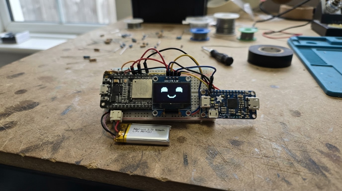
Build a tiny IoT companion that fits on a keychain and displays an animated face on a small OLED screen. The ESP32 microcontroller connects to WiFi and drives expressive eyes and a mouth that react to the network status, complete with natural blinking and winking animations.
This guide provides a complete parts list, wiring diagram, and step-by-step assembly instructions for creating a compact, battery-powered device. The included Arduino firmware handles WiFi connectivity, animation timing, and display rendering, so builders can customize expressions and behavior to match their style.
Wiring diagram

Gather all the parts
Assemble it in 5 steps
1. Prepare the compact parts
Use an ESP32 DevKit v1, a 0.96-inch 128×64 I²C SSD1306 OLED, a protected 3.7 V 500 mAh LiPo pouch battery, and a PowerBoost 1000 Charger module. Do all wiring with the battery disconnected.
- For a smaller finished keychain, mount the display behind a window in a 3D-printed or laser-cut case.
- Keep the ESP32 antenna end clear of battery foil and metal hardware for better Wi-Fi reception.
- Never puncture, crush, or solder directly onto the LiPo battery pouch.
- Use only a protected 3.7 V single-cell LiPo battery with the charging board.
2. Wire the OLED face display
Connect OLED VCC to the ESP32 3V3 pin and OLED GND to an ESP32 GND pin. Connect OLED SDA to GPIO 21 and OLED SCL to GPIO 22. These are 3.3 V I²C connections; do not use 5 V for this display in this design.
- Most 0.96-inch SSD1306 modules use I²C address 0x3C, which is the address used by the firmware.
- Keep these four display wires short to make the keychain more reliable.
- Check the OLED labels carefully: swapping VCC and GND can damage the display.
3. Wire the rechargeable power module
Connect battery positive (+) to the PowerBoost BAT pin and battery negative (-) to PowerBoost GND. Connect the PowerBoost 5V output to the ESP32 VIN/5V pin. The PowerBoost ground and the ESP32 ground must be common; use the PowerBoost GND connection as the shared return. Plug a USB cable only into the PowerBoost USB input when charging.
- The PowerBoost provides a regulated supply suitable for the ESP32 VIN pin.
- A small inline switch between the PowerBoost 5V output and ESP32 VIN is optional if you want a physical off switch.
- Do not connect the LiPo directly to ESP32 VIN or 3V3.
- Do not charge the LiPo from an unprotected, damaged, or swollen battery.
- The PowerBoost USB connector is the charging connector; it is not the ESP32 programming port.
4. Set up the animated face
Before deploying, replace YOUR_WIFI_NAME and YOUR_WIFI_PASSWORD in the firmware with the Wi-Fi credentials for the network the keychain should join. Then use Schematik’s Deploy button to compile and flash it through the ESP32’s own USB connector. The OLED shows a smiling face while online, with periodic blinks and winks; it shows a straight mouth while it is trying to connect.
- Use a 2.4 GHz Wi-Fi network; the ESP32 DevKit v1 does not join 5 GHz-only networks.
- If you leave the placeholder Wi-Fi name in place, the face still animates but does not attempt to join Wi-Fi.
- Disconnect the battery or turn the optional switch off while rearranging wiring.
5. Finish the keychain enclosure
Secure the display, ESP32, and charging module so no bare metal can touch the LiPo pouch or each other. Provide access to the PowerBoost charging connector and the ESP32 programming connector. Fit a lightweight keyring loop to the enclosure rather than directly through a circuit board.
- Use foam tape or a printed battery pocket to prevent the LiPo from moving.
- Avoid enclosing the ESP32 antenna area in metal.
- Inspect for loose wire strands and shorts before reconnecting the battery.
Review all connections
1. Connections between "face_oled" and "ESP32"
2. Connections between "battery" and "ESP32"
3. Connections between "power_boost" and "ESP32"
Deploy the firmware
#include <Arduino.h>
#include <Wire.h>
#include <WiFi.h>
#include <Adafruit_GFX.h>
#include <Adafruit_SSD1306.h>


// Forward declarations
void drawEye(int centerX, bool closed);
void drawMouth(bool online);
void drawStatus(bool online);
void connectWiFi();

constexpr int OLED_SDA_PIN = 21;
constexpr int OLED_SCL_PIN = 22;
constexpr uint8_t OLED_ADDRESS = 0x3C;
constexpr int SCREEN_WIDTH = 128;
constexpr int SCREEN_HEIGHT = 64;
constexpr unsigned long FRAME_INTERVAL_MS = 50;
constexpr unsigned long BLINK_INTERVAL_MS = 3500;
constexpr unsigned long BLINK_LENGTH_MS = 180;
constexpr unsigned long WINK_INTERVAL_MS = 11500;
constexpr unsigned long WINK_LENGTH_MS = 420;

// Enter the Wi-Fi network the keychain should join.
const char *WIFI_SSID = "YOUR_WIFI_NAME";
const char *WIFI_PASSWORD = "YOUR_WIFI_PASSWORD";

Adafruit_SSD1306 display(SCREEN_WIDTH, SCREEN_HEIGHT, &Wire, -1);

unsigned long lastFrameMs = 0;
unsigned long lastBlinkStartMs = 0;
unsigned long lastWinkStartMs = 0;
bool previousLeftClosed = false;
bool previousRightClosed = false;
bool previousOnline = false;
bool initialDraw = true;

void drawEye(int centerX, bool closed) {
  const int eyeTop = 16;
  const int eyeWidth = 30;
  const int eyeHeight = 24;
  display.fillRect(centerX - (eyeWidth / 2) - 2, eyeTop - 2, eyeWidth + 4, eyeHeight + 7, SSD1306_BLACK);

  if (closed) {
    display.drawLine(centerX - 13, 37, centerX + 13, 37, SSD1306_WHITE);
    display.drawLine(centerX - 11, 38, centerX + 11, 38, SSD1306_WHITE);
  } else {
    display.fillRoundRect(centerX - 15, eyeTop, eyeWidth, eyeHeight, 10, SSD1306_WHITE);
    display.fillRoundRect(centerX - 5, eyeTop + 5, 10, 15, 5, SSD1306_BLACK);
  }
}

void drawMouth(bool online) {
  display.fillRect(30, 46, 68, 15, SSD1306_BLACK);
  if (online) {
    display.drawLine(43, 51, 48, 55, SSD1306_WHITE);
    display.drawLine(48, 55, 64, 57, SSD1306_WHITE);
    display.drawLine(64, 57, 80, 55, SSD1306_WHITE);
    display.drawLine(80, 55, 85, 51, SSD1306_WHITE);
  } else {
    display.drawLine(43, 56, 85, 56, SSD1306_WHITE);
  }
}

void drawStatus(bool online) {
  display.fillRect(0, 0, SCREEN_WIDTH, 10, SSD1306_BLACK);
  display.setTextSize(1);
  display.setTextColor(SSD1306_WHITE);
  display.setCursor(2, 1);
  display.print(online ? "WiFi :)" : "WiFi ...");
}

void connectWiFi() {
  if (strcmp(WIFI_SSID, "YOUR_WIFI_NAME") == 0) {
    return;
  }
  WiFi.mode(WIFI_STA);
  WiFi.begin(WIFI_SSID, WIFI_PASSWORD);
}

void setup() {
  Wire.begin(OLED_SDA_PIN, OLED_SCL_PIN);
  if (!display.begin(SSD1306_SWITCHCAPVCC, OLED_ADDRESS)) {
    while (true) {
      delay(1000);
    }
  }
  display.clearDisplay();
  display.display();
  connectWiFi();
}

void loop() {
  const unsigned long now = millis();
  const bool online = WiFi.status() == WL_CONNECTED;

  if (now - lastBlinkStartMs >= BLINK_INTERVAL_MS) {
    lastBlinkStartMs = now;
  }
  if (now - lastWinkStartMs >= WINK_INTERVAL_MS) {
    lastWinkStartMs = now;
  }

  const bool blinking = (now - lastBlinkStartMs) < BLINK_LENGTH_MS;
  const bool winking = (now - lastWinkStartMs) < WINK_LENGTH_MS;
  const bool leftClosed = blinking || winking;
  const bool rightClosed = blinking;

  if (initialDraw || now - lastFrameMs >= FRAME_INTERVAL_MS) {
    if (initialDraw) {
      display.clearDisplay();
    }
    if (initialDraw || leftClosed != previousLeftClosed) {
      drawEye(38, leftClosed);
    }
    if (initialDraw || rightClosed != previousRightClosed) {
      drawEye(90, rightClosed);
    }
    if (initialDraw || online != previousOnline) {
      drawMouth(online);
      drawStatus(online);
    }
    if (initialDraw || leftClosed != previousLeftClosed || rightClosed != previousRightClosed || online != previousOnline) {
      display.display();
      previousLeftClosed = leftClosed;
      previousRightClosed = rightClosed;
      previousOnline = online;
      initialDraw = false;
    }
    lastFrameMs = now;
  }

  if (!online && strcmp(WIFI_SSID, "YOUR_WIFI_NAME") != 0 && WiFi.status() == WL_CONNECT_FAILED) {
    WiFi.disconnect();
    WiFi.begin(WIFI_SSID, WIFI_PASSWORD);
  }
}
Remix this project
Make it yours in one click
Open a full copy of this project in your own Schematik workspace — diagram, code, parts, and assembly steps included. Swap the sensor, add features, or redesign the whole thing with AI. The author's original stays untouched.