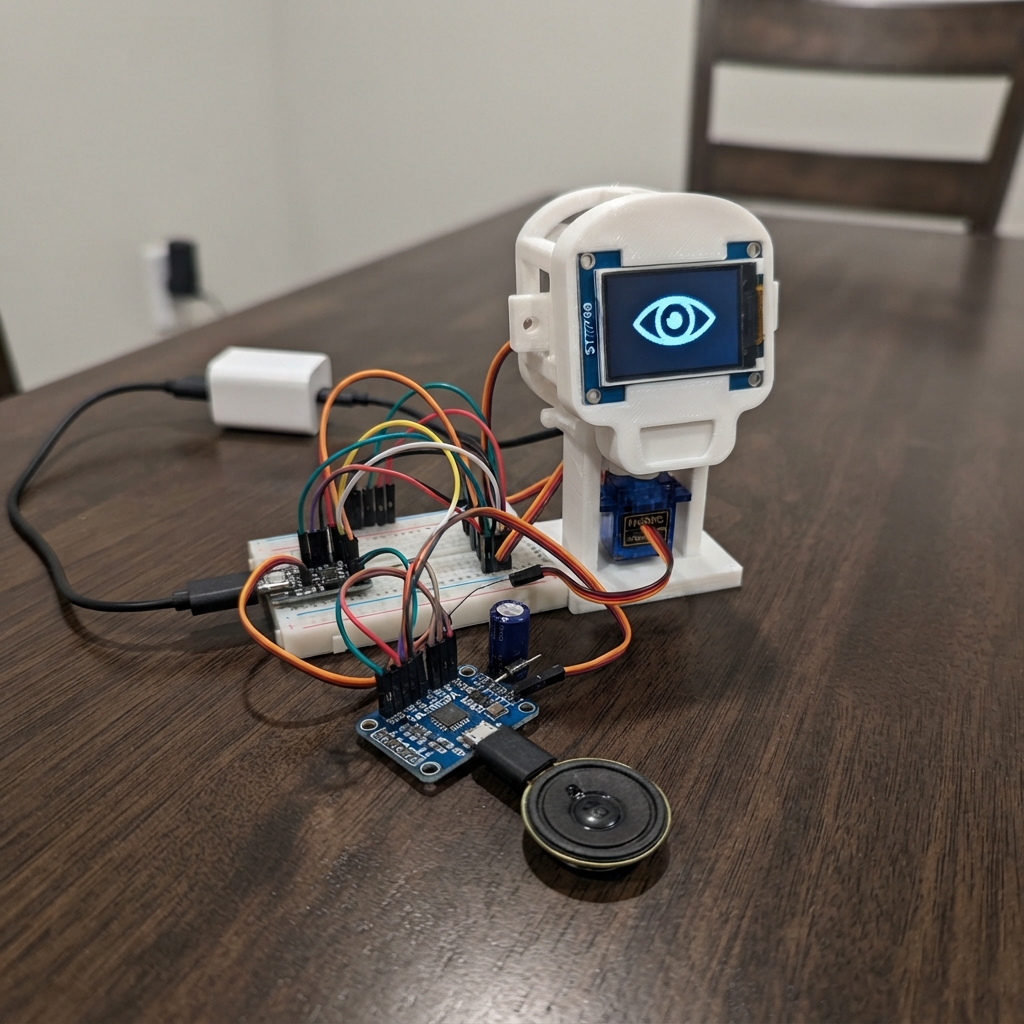
Build an app-controlled animated head that combines servo-driven motion with a colorful TFT face display and audio output. The ESP32 microcontroller manages two MG90S servos for pan and tilt movement, renders expressive animations on a 2-inch ST7789 display, and plays audio through a MAX98357A amplifier and 8Ω speaker.
This guide provides a complete wiring diagram, parts list, and step-by-step assembly instructions that prioritize safe power delivery with protection circuitry. You'll configure the ESP32 firmware to accept motion and expression commands over serial or wireless connection, test each subsystem independently, and integrate everything into a responsive character that moves and speaks on demand.
Wiring diagram
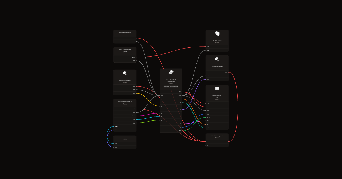
Gather all the parts
Assemble it in 6 steps
1. Make the protected power rail
With every USB cable unplugged, connect the USB-C breakout VBUS terminal to the unbanded end of reverse_diode. The banded end is the protected power point. Connect the 470 µF capacitor with its long positive lead to that banded point and its striped negative lead to GND.
- Do not reverse the capacitor: a reversed electrolytic capacitor can heat, leak, or burst.
- Do not power the external rail while a normal USB cable also connects the XIAO to your Mac; the two 5 V sources can damage the Mac USB port.
2. Join all ground wires
Use a lever or screw terminal to join the USB-C breakout GND, capacitor negative lead, both servo brown or black wires, amplifier GND, display GND, and XIAO GND. This is the shared return path that makes every control signal work.
- Make this ground join first and keep the servo power wires short and thick.
3. Connect protected power
From the diode’s banded end, run one wire to the XIAO 5V/VBUS pin, one to each servo red wire, and one to audio_amp VIN. Do not connect any servo red wire to XIAO 3V3. Connect face_tft VCC and BL to XIAO 3V3.
- The 3.3 V pin powers only the screen logic; it must never power a servo.
4. Wire the face screen
Connect face_tft SCK to XIAO GPIO7/D8 (picture timing), MOSI to GPIO9/D10 (picture data), CS to GPIO44/D7 (screen select), DC to GPIO1/D0 (command/data), and RST to GPIO2/D1 (screen reset). Leave the screen MISO and SDCS disconnected unless the particular display has a card socket you later choose to use.
- This deliberately leaves the Sense expansion camera, microphone, and onboard SD-card connections free.
5. Wire sound and motion
Connect audio_amp BCLK to GPIO5/D4 (sound timing), LRC to GPIO6/D5 (sound sample timing), and DIN to GPIO43/D6 (sound data). Connect amplifier SPK+ and SPK- directly to the two face_speaker terminals. Connect pan_servo orange/yellow signal to GPIO3/D2 and tilt_servo orange/yellow signal to GPIO4/D3.
- Never connect either speaker lead to GND; the amplifier drives both speaker wires.
- Leave both servo horns off for the first power-up so a wrong direction cannot force the printed neck.
6. Test in safe order
First test the screen with the servos unplugged. Next connect the speaker, then verify the built-in Sense microphone and camera in firmware, then plug in one servo at a time with its horn still loose. Fit each horn only after the home position is correct.
- Use the external charger for powered tests; unplug it before connecting a normal USB cable to the Mac for flashing.
Review all connections
1. Connections between "power_supply" and "ESP32"
2. Connections between "reverse_diode" and "ESP32"
3. Connections between "bulk_cap" and "ESP32"
4. Connections between "pan_servo" and "ESP32"
5. Connections between "tilt_servo" and "ESP32"
6. Connections between "audio_amp" and "ESP32"
7. Connections between "face_tft" and "ESP32"
8. Connections between "power_entry" and "ESP32"
Deploy the firmware
#include <Arduino.h>
#include <Arduino_GFX_Library.h>
#include "driver/i2s.h"
#include <math.h>

#define TFT_SCK 7
#define TFT_MOSI 9
#define TFT_CS 44
#define TFT_DC 1
#define TFT_RST 2
#define PAN_SERVO_PIN 3
#define TILT_SERVO_PIN 4
#define I2S_BCLK 5
#define I2S_LRC 6
#define I2S_DIN 43
#define SERIAL_BAUD 115200
#define AUDIO_SAMPLE_RATE 16000
#define SERVO_FREQUENCY 50
#define SERVO_RESOLUTION 16
#define SERVO_MIN_US 500
#define SERVO_MAX_US 2500

Arduino_DataBus *displayBus = new Arduino_ESP32SPI(TFT_DC, TFT_CS, TFT_SCK, TFT_MOSI, GFX_NOT_DEFINED);
Arduino_GFX *gfx = new Arduino_ST7789(displayBus, TFT_RST, 0, true);

int panAngle = 90;
int tiltAngle = 90;
String faceName = "NEUTRAL";
String commandLine;

uint32_t servoDutyFromAngle(int angle) {
  angle = constrain(angle, 20, 160);
  const uint32_t pulseUs = map(angle, 0, 180, SERVO_MIN_US, SERVO_MAX_US);
  return (pulseUs * 65535UL) / 20000UL;
}

void writeServo(int pin, int angle) {
  ledcWrite(pin, servoDutyFromAngle(angle));
}

void setPan(int angle) {
  panAngle = constrain(angle, 20, 160);
  writeServo(PAN_SERVO_PIN, panAngle);
}

void setTilt(int angle) {
  tiltAngle = constrain(angle, 20, 160);
  writeServo(TILT_SERVO_PIN, tiltAngle);
}

void drawEye(int x, int y, bool happy, bool sad) {
  const uint16_t eyeColor = 0xFFFF;
  if (happy) {
    gfx->fillCircle(x, y + 12, 34, eyeColor);
    gfx->fillRect(x - 40, y - 30, 80, 36, 0x0000);
  } else if (sad) {
    gfx->fillCircle(x, y - 12, 34, eyeColor);
    gfx->fillRect(x - 40, y - 6, 80, 36, 0x0000);
  } else {
    gfx->fillRoundRect(x - 30, y - 44, 60, 88, 28, eyeColor);
  }
}

void drawFace() {
  const bool happy = faceName == "HAPPY";
  const bool sad = faceName == "SAD";
  gfx->fillScreen(0x0000);
  drawEye(92, 165, happy, sad);
  drawEye(228, 165, happy, sad);
  if (happy) {
    gfx->drawArc(160, 285, 76, 52, 20, 160, 0xFFE0);
    gfx->drawArc(160, 286, 75, 51, 20, 160, 0xFFE0);
  } else if (sad) {
    gfx->drawArc(160, 350, 76, 52, 200, 340, 0xFFE0);
    gfx->drawArc(160, 349, 75, 51, 200, 340, 0xFFE0);
  } else {
    gfx->fillRoundRect(108, 300, 104, 16, 8, 0xFFE0);
  }
}

void initialiseAudio() {
  i2s_config_t config = {};
  config.mode = (i2s_mode_t)(I2S_MODE_MASTER | I2S_MODE_TX);
  config.sample_rate = AUDIO_SAMPLE_RATE;
  config.bits_per_sample = I2S_BITS_PER_SAMPLE_16BIT;
  config.channel_format = I2S_CHANNEL_FMT_ONLY_LEFT;
  config.communication_format = I2S_COMM_FORMAT_STAND_I2S;
  config.dma_buf_count = 8;
  config.dma_buf_len = 64;
  config.tx_desc_auto_clear = true;
  i2s_pin_config_t pins = {};
  pins.bck_io_num = I2S_BCLK;
  pins.ws_io_num = I2S_LRC;
  pins.data_out_num = I2S_DIN;
  pins.data_in_num = I2S_PIN_NO_CHANGE;
  i2s_driver_install(I2S_NUM_0, &config, 0, nullptr);
  i2s_set_pin(I2S_NUM_0, &pins);
  i2s_zero_dma_buffer(I2S_NUM_0);
}

void playBeep(uint16_t frequency = 660, uint16_t durationMs = 140) {
  const int samples = AUDIO_SAMPLE_RATE * durationMs / 1000;
  int16_t buffer[128];
  int made = 0;
  while (made < samples) {
    const int count = min(128, samples - made);
    for (int i = 0; i < count; ++i) {
      const float phase = 2.0f * PI * frequency * (made + i) / AUDIO_SAMPLE_RATE;
      buffer[i] = (int16_t)(sinf(phase) * 10000.0f);
    }
    size_t written = 0;
    i2s_write(I2S_NUM_0, buffer, count * sizeof(int16_t), &written, portMAX_DELAY);
    made += count;
  }
}

void sendState() {
  Serial.printf("STATE PAN=%d TILT=%d FACE=%s\n", panAngle, tiltAngle, faceName.c_str());
}

void handleCommand(String line) {
  line.trim();
  line.toUpperCase();
  if (line.startsWith("PAN=")) {
    setPan(line.substring(4).toInt());
    Serial.printf("OK PAN=%d\n", panAngle);
  } else if (line.startsWith("TILT=")) {
    setTilt(line.substring(5).toInt());
    Serial.printf("OK TILT=%d\n", tiltAngle);
  } else if (line.startsWith("FACE=")) {
    const String requestedFace = line.substring(5);
    if (requestedFace == "NEUTRAL" || requestedFace == "HAPPY" || requestedFace == "SAD") {
      if (requestedFace != faceName) {
        faceName = requestedFace;
        drawFace();
      }
      Serial.printf("OK FACE=%s\n", faceName.c_str());
    } else {
      Serial.println("ERR FACE must be NEUTRAL, HAPPY, or SAD");
    }
  } else if (line == "SOUND=BEEP") {
    playBeep();
    Serial.println("OK SOUND=BEEP");
  } else if (line == "STATE?") {
    sendState();
  } else if (line.length() > 0) {
    Serial.println("ERR Use PAN=20..160, TILT=20..160, FACE=NEUTRAL|HAPPY|SAD, SOUND=BEEP, or STATE?");
  }
}

void setup() {
  Serial.begin(SERIAL_BAUD);
  delay(300);
  ledcAttach(PAN_SERVO_PIN, SERVO_FREQUENCY, SERVO_RESOLUTION);
  ledcAttach(TILT_SERVO_PIN, SERVO_FREQUENCY, SERVO_RESOLUTION);
  setPan(panAngle);
  setTilt(tiltAngle);
  gfx->begin();
  drawFace();
  initialiseAudio();
  Serial.println("HEAD READY");
  sendState();
}

void loop() {
  while (Serial.available()) {
    const char incoming = (char)Serial.read();
    if (incoming == '\n' || incoming == '\r') {
      if (commandLine.length() > 0) {
        handleCommand(commandLine);
        commandLine = "";
      }
    } else if (commandLine.length() < 80) {
      commandLine += incoming;
    }
  }
  delay(1);
}
Remix this project
Make it yours in one click
Open a full copy of this project in your own Schematik workspace, diagram, code, parts, and assembly steps included. Swap the sensor, add features, or redesign the whole thing with AI. The author's original stays untouched.