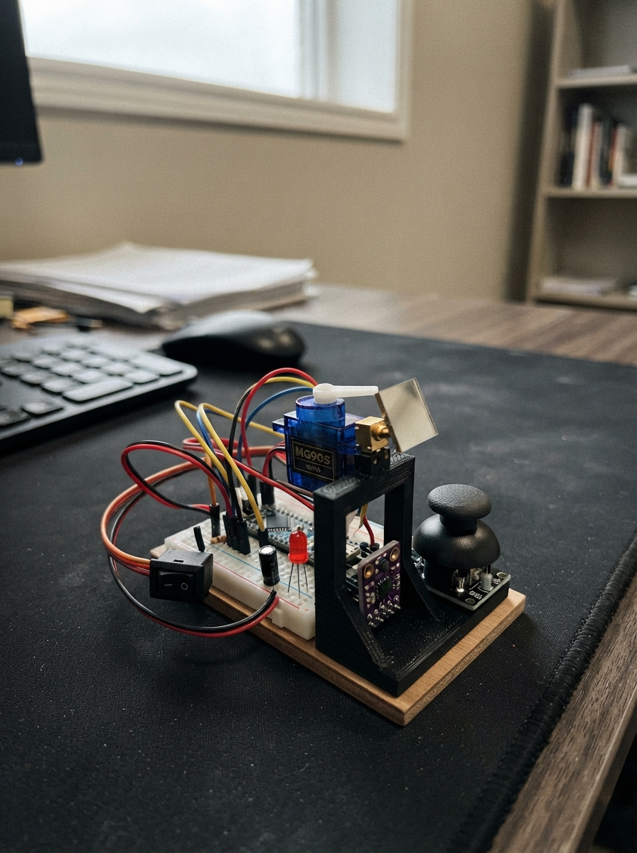
This project builds a computer-controlled laser mirror mount that responds to hand gestures and joystick input. The system uses two servo motors to tilt a mirror in two axes, with a time-of-flight distance sensor to detect hand presence and adjust beam direction accordingly. A status LED and safety switch provide visual feedback and manual control.
The guide includes a complete wiring diagram showing how to connect the servos, joystick, distance sensor, and laser to the ESP32 with proper signal buffering and power distribution. Assembly steps cover building an optical test enclosure, mechanically centering the mirror before installing servo horns, and safely restricting the laser range before operation. Firmware is provided with configurable angle limits and network support for future multi-module systems.
Wiring diagram
Gather all the parts
Assemble it in 8 steps
1. Build a contained optical test area
Use a rigid base, opaque side shields and non-reflective beam stops catching both missed-mirror and reflected beams at all positions, including startup and failure. Place the wall target outside all eye lines. Keep people and animals out of the beam area. Mount the hand sensor outside that area. This is a supervised prototype, not a public installation.
- Never stare into a Class 2 beam or aim it at eyes. A mirror redirects the hazard. Software limits are not a safety interlock.
2. Wire the separate power rail
With all power unplugged, connect a regulated isolated 5 V / 3 A supply to both servo red leads. Connect brown/black servo leads and supply negative to common ground, then ESP32 GND. Put the 1000 uF capacitor next to the servo connectors, plus to external 5 V and stripe/minus to ground. Use a terminal block and short power wires, not breadboard tracks for servo current. ESP32 receives USB power separately. Never connect external positive to board 5V or USB.
- Reverse capacitor polarity can rupture it. Do not open or wire mains supplies.
3. Buffer both servo signals
Fit the 74AHCT125 DIP with notch oriented to its pin diagram: VCC pin 14 to external 5 V, GND pin 7 to ground. Place 100 nF across these pins. GPIO18 to 1A pin 2, 1Y pin 3 to pan signal; GPIO19 to 2A pin 5, 2Y pin 6 to tilt signal. Tie 1OE pin 1 and 2OE pin 4 low. Tie unused 3A pin 9 and 4A pin 12 low, 3OE pin 10 and 4OE pin 13 high; leave unused outputs open.
4. Connect hand sensor and joystick
Use a Pololu VL53L1X carrier with regulator and I2C pull-ups. VIN to 3V3, GND to ground, SDA to GPIO21 (data), SCL to GPIO22 (clock). Leave XSHUT and INT open. Joystick +5V-labelled pin goes to 3V3, not 5 V; GND to ground, VRX to GPIO32, VRY to GPIO33, SW to GPIO27. Powering the joystick at 3.3 V keeps both analog outputs safe.
5. Add the status light
GPIO23 to the 330 ohm resistor, resistor to LED long leg/anode, LED short leg/cathode to ground. One, two or three short flashes show manual, presence or network; rapid continuous flashes mean a latched fault.
6. Wire the normally off laser switch
Keep the rocker OFF. External 5 V goes through the rocker to the Picotronic red lead. Black lead goes to AO3400A drain (pin 3), source (pin 2) to ground. GPIO25 goes through 220 ohm to gate (pin 1). Connect 10 kohm between gate and ground. Use a labelled SOT-23 breakout with no extra circuit to make soldering easier. Insulate the laser housing: its metal case is electrically positive, despite the shop title. Verify polarity and never exceed 5 V.
- Do not substitute an unverified KY-008 or a 5 mW module. The switch must interrupt laser power physically.
7. Centre the mechanics before fitting horns
Leave the laser switch OFF and servo horns detached for the first powered centring test. Once servos hold centre, disconnect power without rotating shafts, fit horns and assemble the standard two-axis bracket. Glue the back of the 30x30 mm front-surface mirror to the tilt plate with compatible adhesive and let it cure. Keep adhesive off the coated face. Aim the fixed laser downward at the mirror centre; orient the neutral mirror approximately 45 degrees to reflect toward the wall. Mechanically check the full allowed range for cable snagging and collisions.
8. Restrict the optical range before laser testing
Start with tight software limits and test motion with laser power OFF. Reduce limits wherever the beam would miss the mirror or any beam stop. A small fixed mirror may not intercept the beam throughout +/-30 degrees; those defaults are not permission to illuminate the whole range. Only enable the rocker for a supervised test after verifying containment. Do not place a hand in the optical path.
Review all connections
1. Connections between "pan" and "ESP32"
2. Connections between "tilt" and "ESP32"
3. Connections between "supply" and "ESP32"
4. Connections between "bulk" and "ESP32"
5. Connections between "tof" and "ESP32"
6. Connections between "stick" and "ESP32"
7. Connections between "status" and "ESP32"
8. Connections between "ledR" and "ESP32"
9. Connections between "gateR" and "ESP32"
10. Connections between "pullR" and "ESP32"
11. Connections between "fet" and "ESP32"
12. Connections between "laser" and "ESP32"
13. Connections between "laserSwitch" and "ESP32"
14. Connections between "buffer" and "ESP32"
15. Connections between "bypass" and "ESP32"
Deploy the firmware
#include <Arduino.h>
#include <Wire.h>
#include <WiFi.h>
#include <WiFiUdp.h>
#include <Preferences.h>
#include <ESP32Servo.h>
#include <VL53L1X.h>
#include <math.h>
// All angles are relative to the mechanically aligned centre, not beam angles.
// Reflected beam angles change by roughly twice the mirror rotation.
constexpr int LASER=25, LED=23, BUTTON=27;
constexpr uint32_t TIMEOUT=3000;
Preferences prefs; WiFiUDP udp; VL53L1X sensor;
bool fault=false, sensorOK=false, manualLaser=false, netLaser=false;
uint8_t mode=0; uint32_t handAt=0, poseAt=0, laserAt=0, sensorAt=0;
bool handSeen=false, poseSeen=false, laserSeen=false;
float distanceMM=500;
struct Axis {
  float offset=0, lo=-30, hi=30, pos=0, vel=0, target=0;
  int lastPulse=-1;
};
struct Module { uint8_t id; Axis axes[2]; };
Module modules[]={{1,{Axis(),Axis()}}}; // Future grid: add IDs 2,3,4 here.
constexpr size_t COUNT=sizeof(modules)/sizeof(modules[0]);
Servo servos[2];
float clampf(float x,float a,float b){ return fminf(b,fmaxf(a,x)); }
void trip(const char *why){ digitalWrite(LASER,LOW); fault=true; manualLaser=netLaser=false; Serial.printf("ERROR: %s; reset after correcting\n",why); }
// Only this adapter knows about physical servo hardware. A future PCA9685
// adapter maps module index*2+axis to its 50 Hz PWM channels, with I2C error checks.
void writePulse(size_t module,int axis,int us){
  if(module==0) servos[axis].writeMicroseconds(us);
}
void setMode(int m){ digitalWrite(LASER,LOW); mode=m; manualLaser=netLaser=false; handSeen=poseSeen=laserSeen=false; Serial.printf("Mode %u\n",mode); }
void loadConfig(){
  for(size_t m=0;m<COUNT;m++) for(int a=0;a<2;a++){
    Axis &x=modules[m].axes[a]; char k[16];
    snprintf(k,sizeof(k),"%u-%d-o",modules[m].id,a); x.offset=prefs.getFloat(k,0);
    snprintf(k,sizeof(k),"%u-%d-l",modules[m].id,a); x.lo=prefs.getFloat(k,-30);
    snprintf(k,sizeof(k),"%u-%d-h",modules[m].id,a); x.hi=prefs.getFloat(k,30);
    if(!isfinite(x.offset)||!isfinite(x.lo)||!isfinite(x.hi)||x.lo>0||x.hi<0||x.lo>=x.hi||fabsf(x.offset)>30||x.lo< -60||x.hi>60||x.lo+x.offset< -80||x.hi+x.offset>80) trip("invalid stored limits");
  }
}
// Bounded, non-blocking serial line reader. No flash writes during motion.
void serialInput(){
  static char line[160]; static size_t n=0;
  for(int budget=0;Serial.available()&&budget<64;budget++){
    char c=Serial.read(); if(c=='\r')continue;
    if(c!='\n'){ if(n<sizeof(line)-1)line[n++]=c; else {n=0;trip("serial line too long");} continue; }
    line[n]=0;n=0; int id,a,m;float o,l,h;
    if(sscanf(line,"mode %d",&m)==1 && m>=0&&m<=2) setMode(m);
    else if(!strcmp(line,"laser 0")) manualLaser=false;
    else if(!strcmp(line,"laser 1")&&mode==0&&!fault) manualLaser=true;
    else if(sscanf(line,"config %d %d %f %f %f",&id,&a,&o,&l,&h)==5){
      digitalWrite(LASER,LOW); manualLaser=netLaser=false;
      bool valid=false;
      for(auto &mod:modules) if(mod.id==id&&a>=0&&a<2&&isfinite(o)&&isfinite(l)&&isfinite(h)&&fabsf(o)<=30&&l>=-60&&h<=60&&l<=0&&h>=0&&l<h&&l+o>=-80&&h+o<=80){
        Axis &x=mod.axes[a];x.offset=o;x.lo=l;x.hi=h;valid=true;
      }
      Serial.println(valid?"Config staged; use save":"Rejected config");
    } else if(!strcmp(line,"save")){
      digitalWrite(LASER,LOW);manualLaser=netLaser=false;
      for(auto &mod:modules)for(int ax=0;ax<2;ax++){
        Axis &x=mod.axes[ax];char k[16];
        snprintf(k,sizeof(k),"%u-%d-o",mod.id,ax);if(prefs.putFloat(k,x.offset)!=4)trip("flash write");
        snprintf(k,sizeof(k),"%u-%d-l",mod.id,ax);if(prefs.putFloat(k,x.lo)!=4)trip("flash write");
        snprintf(k,sizeof(k),"%u-%d-h",mod.id,ax);if(prefs.putFloat(k,x.hi)!=4)trip("flash write");
      }
      Serial.println("Saved");
    } else if(!strncmp(line,"wifi ",5)){
      // Syntax: wifi SSID|password. Credentials are stored locally in NVS.
      digitalWrite(LASER,LOW);manualLaser=netLaser=false;
      char *sep=strchr(line+5,'|');if(sep){*sep=0;prefs.putString("ssid",line+5);prefs.putString("pass",sep+1);WiFi.begin(line+5,sep+1);}
    } else if(!strcmp(line,"show")){
      Serial.printf("mode=%u fault=%d IP=%s\n",mode,fault,WiFi.localIP().toString().c_str());
      for(auto &mod:modules)for(int ax=0;ax<2;ax++){Axis &x=mod.axes[ax];Serial.printf("ID %u axis %d offset %.2f limits %.2f %.2f\n",mod.id,ax,x.offset,x.lo,x.hi);}
    }else Serial.println("Commands: mode 0..2; laser 0|1; config ID AXIS OFFSET MIN MAX; save; show; wifi SSID|password");
  }
}
// Minimal strict OSC message parser: padded strings, big-endian int32/float32.
// Standalone messages only; OSC bundles are deliberately rejected.
bool oscString(const uint8_t *b,int len,int &p,String &s){
  s=""; int start=p;while(p<len&&b[p]){if(p-start>40)return false;s+=(char)b[p++];}
  if(p>=len)return false;p++;while(p%4){if(p>=len||b[p++]!=0)return false;}return true;
}
bool oscNumber(const uint8_t *b,int len,int &p,char type,float &v){
  if(p+4>len||(type!='f'&&type!='i'))return false;
  uint32_t u=(uint32_t(b[p])<<24)|(uint32_t(b[p+1])<<16)|(uint32_t(b[p+2])<<8)|b[p+3];p+=4;
  if(type=='i')v=(int32_t)u;else memcpy(&v,&u,4);return isfinite(v);
}
void networkInput(){
  int len=udp.parsePacket();if(!len)return;
  uint8_t b[128];if(len>128){while(udp.available())udp.read();if(mode==2)trip("oversized OSC");return;}
  int got=udp.read(b,len),p=0;String addr,tags;float v[2];bool ok=got==len&&oscString(b,len,p,addr)&&oscString(b,len,p,tags);
  bool handled=false;
  for(auto &mod:modules){
    String suffix=String(mod.id);
    if(ok&&addr=="/tilt/"+suffix){
      ok=tags.length()==3&&tags[0]==','&&oscNumber(b,len,p,tags[1],v[0])&&oscNumber(b,len,p,tags[2],v[1])&&p==len;
      if(ok&&mode==2){for(int a=0;a<2;a++)mod.axes[a].target=clampf(v[a],mod.axes[a].lo,mod.axes[a].hi);poseAt=millis();poseSeen=true;}
      handled=true;
    } else if(ok&&addr=="/laser/"+suffix){
      ok=tags.length()==2&&tags[0]==','&&oscNumber(b,len,p,tags[1],v[0])&&p==len&&(v[0]==0||v[0]==1);
      if(ok&&mode==2){netLaser=v[0]==1;laserAt=millis();laserSeen=true;}
      handled=true;
    }
  }
  if(mode==2&&(!ok||!handled))trip("invalid OSC address or payload");
}
void readSensor(){
  if(!sensorOK||fault)return;
  if(sensor.dataReady()){
    uint16_t mm=sensor.read(false);sensorAt=millis();
    if(sensor.timeoutOccurred()||sensor.last_status){trip("ToF communication");return;}
    // Out-of-range is absence, not a hardware fault. Other invalid readings
    // immediately disable emission rather than retaining the previous ON state.
    if(sensor.ranging_data.range_status==VL53L1X::RangeValid){
      distanceMM=distanceMM*0.75f+mm*0.25f;
      if(mm>=40&&mm<500){handAt=millis();handSeen=true;}
    } else { digitalWrite(LASER,LOW);handSeen=false; }
  }
  if(millis()-sensorAt>500)trip("ToF stopped responding");
}
// Acceleration-limited velocity controller with braking-distance planning.
// Fixed 10 ms timestep; small target deadband suppresses ADC/sensor noise.
void moveAxis(size_t m,int a){
  Axis &x=modules[m].axes[a];x.target=clampf(x.target,x.lo,x.hi);
  float e=x.target-x.pos;
  float wanted=(e>=0?1:-1)*fminf(20,sqrtf(2*40*fabsf(e)));
  if(fabsf(e)<0.15f)wanted=0;
  x.vel+=clampf(wanted-x.vel,-0.4f,0.4f);x.pos+=x.vel*0.01f;
  x.pos=clampf(x.pos,x.lo,x.hi);
  int pulse=lroundf(1500+(x.pos+x.offset)*(1000.0f/180.0f));
  pulse=constrain(pulse,1000,2000);
  if(abs(pulse-x.lastPulse)>=2){writePulse(m,a,pulse);x.lastPulse=pulse;}
}
void setup(){
  digitalWrite(LASER,LOW);pinMode(LASER,OUTPUT);pinMode(LED,OUTPUT);pinMode(BUTTON,INPUT_PULLUP);
  Serial.begin(115200);analogReadResolution(12);
  if(!prefs.begin("tilt",false))trip("flash unavailable");else loadConfig();
  for(int a=0;a<2;a++){servos[a].setPeriodHertz(50);servos[a].attach(a==0?18:19,1000,2000);if(!servos[a].attached())trip("servo attach");}
  Wire.begin(21,22);Wire.setTimeOut(30);sensor.setTimeout(100);
  sensorOK=sensor.init();
  if(!sensorOK)trip("ToF init");else{
    if(!sensor.setDistanceMode(VL53L1X::Short)||!sensor.setMeasurementTimingBudget(50000))trip("ToF configuration");
    sensor.startContinuous(60);sensorAt=millis();
  }
  WiFi.mode(WIFI_STA);WiFi.setAutoReconnect(true);
  String ssid=prefs.getString("ssid","");if(ssid.length())WiFi.begin(ssid.c_str(),prefs.getString("pass","").c_str());
  if(!udp.begin(8000))trip("UDP bind");
  Serial.println("Tilt 1 ready. laser OFF. Send help or show at 115200 baud.");
}
void loop(){
  static uint32_t tick=millis(),buttonAt=0;static int rawOld=HIGH,stable=HIGH;
  uint32_t now=millis();
  if(now-tick>100){trip("control loop stalled");tick=now;}
  int raw=digitalRead(BUTTON);if(raw!=rawOld){rawOld=raw;buttonAt=now;}
  if(now-buttonAt>=35&&raw!=stable){stable=raw;if(stable==LOW)setMode((mode+1)%3);}
  serialInput();networkInput();readSensor();
  bool emit=false;
  if(now-tick>=10){tick+=10;
    Module &mod=modules[0];
    if(mode==0){
      for(int a=0;a<2;a++){
        static float filtered[2]={2048,2048};int adc=analogRead(a==0?32:33);
        filtered[a]+=0.15f*(adc-filtered[a]);float t=(filtered[a]-2048)/2048;
        if(fabsf(t)<0.06f)t=0;
        float target=t>=0?t*mod.axes[a].hi:-t*mod.axes[a].lo;
        if(fabsf(target-mod.axes[a].target)>0.3f)mod.axes[a].target=target;
      }
      // A healthy, continuously sampled joystick counts as fresh manual input.
      emit=manualLaser;
    }else if(mode==1){
      bool present=handSeen&&now-handAt<TIMEOUT;
      emit=present;
      if(present){mod.axes[0].target=sinf(now*0.000314159f)*fminf(mod.axes[0].hi,-mod.axes[0].lo);mod.axes[1].target=mod.axes[1].lo+clampf((distanceMM-50)/450,0,1)*(mod.axes[1].hi-mod.axes[1].lo);}
      else for(auto &x:mod.axes)x.target=0;
    }else{
      bool fresh=poseSeen&&laserSeen&&now-poseAt<TIMEOUT&&now-laserAt<TIMEOUT&&WiFi.status()==WL_CONNECTED;
      emit=fresh&&netLaser;
      if(!fresh){netLaser=false;for(auto &x:mod.axes)x.target=0;}
    }
    if(fault){emit=false;for(auto &x:mod.axes)x.target=0;}
    for(size_t m=0;m<COUNT;m++)for(int a=0;a<2;a++)moveAxis(m,a);
    digitalWrite(LASER,emit&&!fault?HIGH:LOW);
  }
  uint32_t phase=now%2000;
  digitalWrite(LED,fault?(now%200<100):(phase<(mode+1)*300&&phase%300<100));
}
Remix this project
Make it yours in one click
Open a full copy of this project in your own Schematik workspace, diagram, code, parts, and assembly steps included. Swap the sensor, add features, or redesign the whole thing with AI. The author's original stays untouched.