Community project
Arduino LED Signage
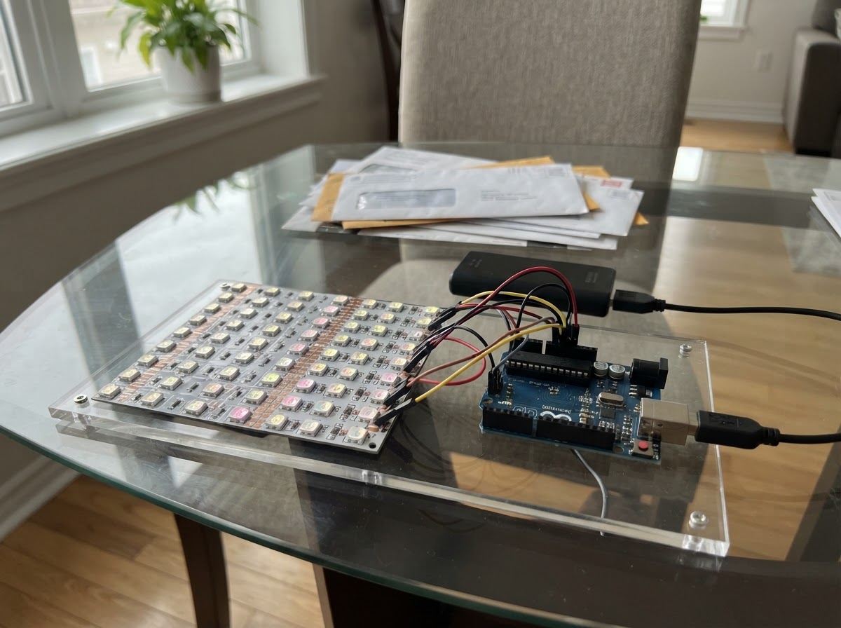
Build a simple LED sign that displays the word HELLO with an eye-catching animation. This project uses five individual LEDs controlled by an Arduino Uno to light up letters in sequence, creating a welcoming display that cycles through a pattern to grab attention.
The guide includes a complete wiring diagram, parts list with resistor values, and ready-to-upload firmware. Assembly takes just a few minutes: arrange the LEDs to spell out the letters, wire each through a current-limiting resistor to the Arduino pins, connect all cathodes to ground, and power it up to see the sign in action.
Wiring diagram

Gather all the parts
Assemble it in 5 steps
1. Lay out the word
On a breadboard or sign panel, place five LEDs in positions that form the word HELLO. Label them H, E, first L, second L, and O so the wires stay identifiable.
- Use the same LED colour for a consistent-looking sign.
- For a panel, make letter shapes from several LEDs later; this starter build uses one LED as each letter indicator.
- The longer LED leg is normally the anode (+); the shorter leg and flat edge mark the cathode (–).
2. Connect the LED cathodes to ground
Connect the cathode (short leg) of every LED to an Arduino GND pin. A shared ground rail on the breadboard is convenient.
- All five LED cathodes may share the same ground rail.
- Keep the Arduino disconnected from USB while changing wiring.
3. Add a resistor to every LED anode
Connect one separate 220 Ω resistor in series with the anode (long leg) of each LED. Never connect an LED directly to an Arduino output pin.
- A 220 Ω to 330 Ω resistor is suitable for typical red, yellow, or green LEDs on an Uno.
- The resistor may be placed on either side of an LED electrically, but placing it between the Arduino pin and anode makes the wiring easier to check.
- Each LED requires its own resistor; do not share one resistor among multiple LEDs.
4. Connect the five letter inputs
From the free end of each resistor, connect H to D2, E to D3, the first L to D4, the second L to D5, and O to D6 on the Arduino Uno.
- Avoid D0 and D1 because they are used for USB serial communication.
- Check each connection against the letter label before powering the board.
- Do not connect LEDs to the 5 V rail for this animated design; the Arduino digital pins control them.
5. Power and observe the sign
Connect the Arduino Uno to its USB port. Use Schematik’s Deploy button to flash the project. The LEDs will light H-E-L-L-O one at a time, remain on as a complete word, then repeat.
- If a letter does not illuminate, unplug USB and first reverse that LED; LEDs are polarity-sensitive.
- USB power is sufficient for these five indicator LEDs with the specified resistors.
Review all connections
1. Connections between "led_h" and "Arduino"
2. Connections between "led_e" and "Arduino"
3. Connections between "led_l1" and "Arduino"
4. Connections between "led_l2" and "Arduino"
5. Connections between "led_o" and "Arduino"
Deploy the firmware
#include <Arduino.h>
// Fixed-word LED sign: H E L L O
// Each LED anode is connected through its own 220-ohm resistor.


// Forward declarations
void setAllLetters(uint8_t state);

const uint8_t H_LED_PIN = 2;
const uint8_t E_LED_PIN = 3;
const uint8_t L1_LED_PIN = 4;
const uint8_t L2_LED_PIN = 5;
const uint8_t O_LED_PIN = 6;

const uint8_t letterPins[] = {
  H_LED_PIN, E_LED_PIN, L1_LED_PIN, L2_LED_PIN, O_LED_PIN
};
const uint8_t LETTER_COUNT = sizeof(letterPins) / sizeof(letterPins[0]);

void setAllLetters(uint8_t state) {
  for (uint8_t i = 0; i < LETTER_COUNT; i++) {
    digitalWrite(letterPins[i], state);
  }
}

void setup() {
  for (uint8_t i = 0; i < LETTER_COUNT; i++) {
    pinMode(letterPins[i], OUTPUT);
  }
  setAllLetters(LOW);
}

void loop() {
  // Light H-E-L-L-O in sequence to attract attention.
  for (uint8_t i = 0; i < LETTER_COUNT; i++) {
    digitalWrite(letterPins[i], HIGH);
    delay(250);
  }

  // Keep the completed word visible briefly.
  delay(1500);

  // Turn the sign off before repeating the animation.
  setAllLetters(LOW);
  delay(500);
}
Remix this project
Make it yours in one click
Open a full copy of this project in your own Schematik workspace — diagram, code, parts, and assembly steps included. Swap the sensor, add features, or redesign the whole thing with AI. The author's original stays untouched.