Community project
Proximity Distance Indicator
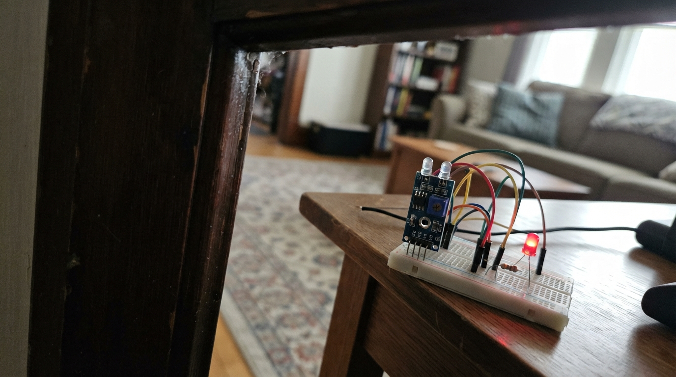
This proximity distance indicator uses an infrared obstacle detection module to sense nearby objects and provide visual feedback through an LED. When the FC-51 sensor detects an object within its adjustable range, the red LED illuminates to alert the user.
The guide includes a complete parts list, wiring diagram showing connections between the Arduino Uno, sensor module, and LED circuit, step-by-step assembly instructions, and the firmware needed to run the project. Builders will learn how to wire an LED with current-limiting resistor, interface with an IR sensor module, and program basic digital input/output on an Arduino.
Wiring diagram
Gather all the parts
Assemble it in 4 steps
1. Prepare the single red LED circuit
Unplug USB before changing wires. The diagram contains only the Uno, the FC-51 IR obstacle sensor, one red LED, and one 330 ohm resistor. Disconnect any parts from the previous build that are not shown. The sensor has two front bulbs and three labelled pins.
2. Connect the obstacle sensor
Connect VCC to Uno 5V (power), GND to Uno GND (shared return), and OUT to D2 (object detection signal). Follow the printed pin labels, not the left-to-right position.
- Reversing VCC and GND can damage the sensor.
3. Connect the red light
Connect Uno D4 to one end of the 330 ohm resistor. Connect its other end to the red LED's long leg (anode). Connect the short leg (flat side) to GND.
- The resistor is required to protect the LED and the Uno output.
4. Adjust detection range
Place an object in front of the two sensor bulbs and gently adjust the small screw until the detection indicator changes. The external red LED lights while an object is detected and turns off when it is removed.
- Detection depends on object colour and room lighting; avoid direct sunlight. This module detects presence rather than measuring distance.
Review all connections
1. Connections between "ir" and "Arduino"
2. Connections between "r_red" and "Arduino"
3. Connections between "red" and "Arduino"
Deploy the firmware
#include <Arduino.h>
const uint8_t SENSOR_PIN = 2;
const uint8_t RED_LED_PIN = 4;

void setup() {
  digitalWrite(RED_LED_PIN, LOW);
  pinMode(RED_LED_PIN, OUTPUT);
  pinMode(SENSOR_PIN, INPUT_PULLUP);
}

void loop() {
  const bool detected = digitalRead(SENSOR_PIN) == LOW;
  digitalWrite(RED_LED_PIN, detected ? HIGH : LOW);
  delay(10);
}
Remix this project
Make it yours in one click
Open a full copy of this project in your own Schematik workspace, diagram, code, parts, and assembly steps included. Swap the sensor, add features, or redesign the whole thing with AI. The author's original stays untouched.