Community project
Automatic Waste Sorting Machine
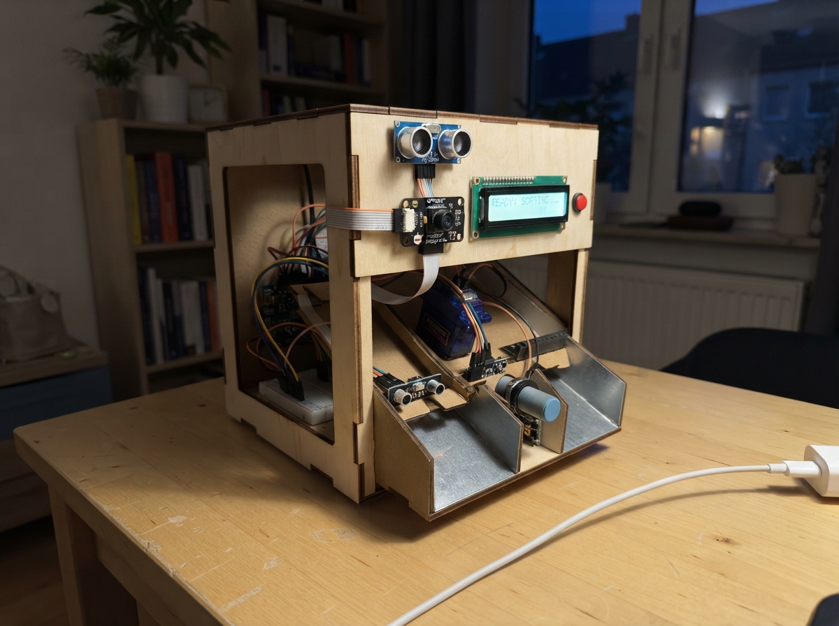
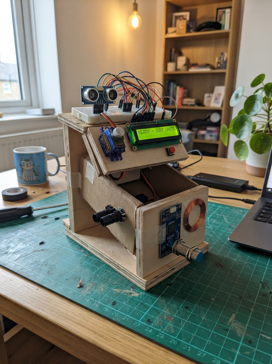
This automatic waste sorting machine uses computer vision and sensors to identify and route different types of waste into separate bins. Built around an Arduino Uno, the system combines a rotating tube mechanism, servo-controlled gate, HuskyLens AI camera for material classification, and multiple sensors including an inductive metal detector, IR break-beam pair, and ultrasonic distance sensor to detect, identify, and sort incoming items.
The guide provides a complete wiring diagram, parts list, and step-by-step assembly instructions for constructing the mechanical sorting tube, positioning the collection bins, and integrating all electrical components. Included is the full Arduino firmware with state machine logic for controlling the sorting workflow, plus calibration procedures and camera training steps to get the system operational with your chosen waste categories.
Wiring diagram
Gather all the parts
Assemble it in 11 steps
1. Build a light rotating tube
Use exactly two standard positional MG996R servos, not continuous-rotation versions. Mount a lightweight holding tube on a bearing-supported turntable. Servo 1 turns only the tube through a linkage. Fit a hinged bottom gate operated by Servo 2, with a mechanical closed stop. Bearings and frame, not servo shafts, must carry the tube and item weight. Use dry, empty single items only.
- Guard all rotating and gate pinch points. Disconnect all supplies before touching a jam. This is a supervised tabletop prototype, not an unattended public machine.
2. Position the three fixed bins
Fix the blue bottle bin at 45 degrees, red can bin at 90 degrees, and green paper bin at 135 degrees relative to the tube servo linkage. Home is initially 90 degrees. Use fixed funnel mouths wide enough to catch the rotating tube outlet. Keep the gate closed during every rotation. Allow flexible wiring with strain relief and enough slack for 45–135 degrees.
- Keep the identification sensors fixed at the home station. The exit beam moves with the outlet just below the gate, so it covers every selected bin path. Fixed bins and funnels never rotate.
3. Distribute servo and camera power
Use an enclosed regulated 5V 8A supply for both servos, and a separate enclosed 5V 2A supply for HuskyLens. Connect servo red wires directly to the servo supply positive using screw-terminal distribution and suitable heavy wire; connect brown/black grounds to its negative. Join this negative and camera supply negative to Uno GND in a star connection. Place the 2200uF 10V capacitor across the servo rail, positive to +5V and marked negative stripe to GND. Tube signal goes to D9 and gate signal to D10. Power Uno through USB.
- Never power either servo from Uno 5V or through a breadboard. Do not join either external 5V positive to Uno 5V or USB. Do not expose or wire mains terminals. Capacitor reversal can cause rupture. Switch off servo power during firmware updates and keep the tube empty at startup.
4. Connect the insertion and exit beams
Use two SEN0503 break-beam kits. For each kit, both red leads go to Uno 5V and both black leads to GND. Entry receiver white OUT goes to D2; exit receiver white OUT to D4. Uno internal pull-ups hold inputs high; blocked beam is low. Align entry beam across the tube mouth and exit beam immediately below the gate, away from the gate's own path. Check both clear and blocked levels before use.
- These beams are specified for opaque objects. Present a bottle label or opaque cap across the beam and restrict bottle sizes/orientations accordingly. Clear plastic can pass undetected: test every allowed bottle. Unconfirmed passages earn zero points.
5. Connect distance and start control
HC-SR04 VCC to 5V and GND to GND; TRIG to D7 sends the ranging pulse, ECHO to D6 receives it. Mount above the tube at home, with the empty gate more than 18cm below and the object surface 2–18cm away. Button SIGNAL to D5 and GND to GND, across the switch contacts that close when pressed. Use a breadboard for low-current connections only.
- Change the distance threshold in src/main.cpp for your tube. The firmware requires three close readings or entry beam blockage. Insert only after the screen says Insert Trash; one press starts one cycle.
6. Isolate the 12V metal detector
Use ONLY the NPN normally-open LJ12A3-4-Z/BX version. Brown goes to enclosed 12V adapter positive, blue to adapter negative. Wire 12V positive through the 2.2k ohm 0.25W resistor to PC817 pin 1 Anode. PC817 pin 2 Cathode connects to sensor black output. On the Uno side, PC817 pin 3 Emitter goes to Uno GND, pin 4 Collector to D3, and a 10k resistor from Collector to Uno 5V. Read PC817 pin numbers from the notch/dot and its datasheet. Keep the isolated 12V negative separate from Uno ground. Metal detection produces LOW on D3.
- Place the sensor beside a nonmetallic guide that holds the side of every accepted can very close to the sensing face. The nominal 4mm rating is for steel; aluminum range is much shorter. Test all accepted cans and adjust the guide; no metal signal means a visually identified can is rejected. Keep screws, gate hardware and servo metal away from the sensing face. Inductive sensing detects metals, not uniquely aluminum; visual class and a restricted set of cans are also required.
- Never connect black, brown, or any 12V wire directly to the Uno. Do not substitute a PNP sensor. This optocoupler circuit is specifically for a 12V supply, not 24V.
7. Connect screen and camera
LCD VCC to Uno 5V, GND to GND, SDA to A4 (data), SCL to A5 (clock). LCD address is initially 0x27; adjust its contrast knob. HuskyLens + goes to the dedicated camera 5V supply, - to common GND, T to A4 (SDA) and R to A5 (SCL). The circuit diagram labels those two camera signals SDA and SCL; the actual camera case labels them T and R. Both devices share the I2C wires; HuskyLens address is 0x32. Select I2C in the camera General Settings.
- If your PCF8574 backpack uses 0x3F rather than 0x27, change the LCD constructor address. Mount the camera fixed at the home identification station, with its view centered on the closed tube, not through reflective plastic walls.
8. Train the identification camera
On HuskyLens select Object Classification and enable Learn Multiple. Start with no old learned objects. Learn IDs in this exact order: 1 plastic bottle, 2 aluminum can, 3 crumpled paper, 4 reject/background. For each ID hold the learning button and show the permitted objects from different angles and distances inside the actual tube. Press learning again during the continue countdown to add the next ID. Include the empty tube and likely invalid objects in the reject class. Keep lighting, background, tube geometry and object sizes consistent.
- Code requires 12 consecutive matching readings, rejects missing/multiple/unsupported IDs and metal/vision disagreement, and times out after six seconds. A can needs both visual ID2 and inductive confirmation. Verify many separate test samples, including unknowns, before enabling sorting. If it confuses bottle and paper, improve training and constrain permitted items; do not simply force a class.
- This camera reports class IDs without a calibrated confidence score. Twelve consistent readings are a stability test, not proof of material or reliable rejection of arbitrary unseen waste. Use only a validated limited set of bottles, aluminum cans and paper. Do not use this prototype to promise universal classification or fraud-proof points.
9. Connect the processing buzzer
Use a self-oscillating 5V active piezo buzzer drawing at most 20mA. Its positive goes to Uno 5V and negative to PN2222A Collector. Emitter goes to GND. D8 goes through 1k ohm to Base; fit 10k ohm between Base and GND. Check the purchased transistor's B/C/E pin order. The transistor avoids loading D8 with the buzzer current.
- Buzzer stays off while waiting for insertion, on during detection, identification, rotation, release and normal return, then off on success or fault. This specifies a piezo buzzer, not an inductive magnetic sounder.
10. Calibrate without trash first
With linkages disconnected, power the controller to establish servo positions, then switch all power off before fitting horns. Align CLOSED=0 and OPEN=90 so the gate clears without forcing an endpoint; change constants if necessary. Set HOME and bin angles to your mechanism. ROTATE_MS=2000 and GATE_MS=900 are initial movement plus settling delays. Test empty movements and lengthen delays for the actual load.
- Hobby servos provide no external arrival or gate-closed feedback. The code waits calibrated times; it cannot detect a stalled servo or verify bin alignment. Restrict loads, use a closed gate stop and inspect alignment. Do not operate if a servo stalls, hums at an endpoint or the gate cannot close. Guards and supervision remain necessary.
11. Test scoring and fault recovery
Try one validated item per button press. Check that the tube turns with gate closed, waits two seconds, then opens. Exit confirmation requires a fresh blocked beam followed by 150ms clear. Only after closing the gate and returning home are exactly two points added, once. Total points are held in RAM and reset to zero when Uno restarts. Confirm the screen returns to Click to Begin and requires a new press.
- For any fault, switch off all supplies, remove the item and clear the path without putting fingers into a powered mechanism. Restore power empty; the score resets. For a non-jammed sensor or unknown-item fault, manually clear with power off, then restart. A released-and-pressed button can also acknowledge a cleared fault; the controller closes the gate before returning home. Never clear a jam while powered.
- An exit beam confirms chute passage, not material identity or arrival inside the bin. Points are not a secure financial reward system. An unknown item stays behind the closed gate at home and earns nothing. After a release timeout the tube deliberately stays over its bin with gate open to avoid pinching a jam; buzzer turns off, zero points are added, and there is no automatic retry.
Review all connections
1. Connections between "sonar" and "Arduino"
2. Connections between "lcd" and "Arduino"
3. Connections between "entry" and "Arduino"
4. Connections between "exit" and "Arduino"
5. Connections between "start" and "Arduino"
6. Connections between "tube" and "Arduino"
7. Connections between "gate" and "Arduino"
8. Connections between "servo_supply" and "Arduino"
9. Connections between "bulk" and "Arduino"
10. Connections between "camera_supply" and "Arduino"
11. Connections between "vision" and "Arduino"
12. Connections between "sensor_supply" and "Arduino"
13. Connections between "metal" and "Arduino"
14. Connections between "opto_r" and "Arduino"
15. Connections between "opto" and "Arduino"
16. Connections between "pullup" and "Arduino"
17. Connections between "buzzer" and "Arduino"
18. Connections between "driver" and "Arduino"
19. Connections between "base_r" and "Arduino"
20. Connections between "base_pd" and "Arduino"
Deploy the firmware
#include <Arduino.h>
#include <Wire.h>
#include <Servo.h>
#include <LiquidCrystal_I2C.h>
#include <HUSKYLENS.h>
#include <limits.h>
// Calibrate with empty mechanisms first. Standard positional servos only.
constexpr uint8_t ENTRY=2, METAL=3, EXIT=4, BUTTON=5, ECHO=6, TRIG=7,
 BUZZER=8, TUBE=9, GATE=10;
constexpr int HOME=90, CLOSED=0, OPEN=90;
const int BIN_ANGLE[4]={HOME,45,90,135};
constexpr unsigned long ROTATE_MS=2000, GATE_MS=900, EXIT_TIMEOUT=7000;
Servo tube, gate;
LiquidCrystal_I2C lcd(0x27,16,2);
HUSKYLENS camera;
enum State {BOOT,IDLE,INSERT,DETECTED,IDENTIFY,LABEL,ROTATE,BASELINE,
 RELEASE,CLOSE_GATE,RETURN_HOME,SUCCESS,TOTAL,FAULT};
State state=BOOT;
unsigned long since=0,lastButton=0,lastSample=0,clearSince=0,blockSince=0;
bool rawButton=HIGH, stableButton=HIGH, armed=false, seenExit=false;
uint8_t kind=0,candidate=0,votes=0,nearVotes=0;
uint32_t points=0;
char oldLines[2][17]={{0},{0}};
void line(uint8_t row,const char *text) {
 char padded[17]; memset(padded,' ',16); padded[16]=0;
 for(uint8_t i=0;i<16 && text[i];i++) padded[i]=text[i];
 if(strcmp(oldLines[row],padded)!=0){lcd.setCursor(0,row);lcd.print(padded);strcpy(oldLines[row],padded);}
}
void show(const __FlashStringHelper *a,const __FlashStringHelper *b) {
 char text[17]; strncpy_P(text,(PGM_P)a,16);text[16]=0;line(0,text);
 strncpy_P(text,(PGM_P)b,16);text[16]=0;line(1,text);
}
void enter(State s){state=s;since=millis();}
void standby(){
 digitalWrite(BUZZER,LOW);show(F("Click to Begin"),F(""));
 char text[17];snprintf(text,sizeof text,"Points: %lu",(unsigned long)points);line(1,text);
 armed=false;enter(IDLE);
}
void fault(const __FlashStringHelper *message){
 // Keep tube stationary. Never sweep a possibly jammed item across bins.
 digitalWrite(BUZZER,LOW);show(message,F("Clear; press btn"));armed=false;enter(FAULT);
}
bool pressed(){
 bool r=digitalRead(BUTTON);unsigned long now=millis();
 if(r!=rawButton){rawButton=r;lastButton=now;}
 bool event=false;
 if(now-lastButton>=35 && stableButton!=r){stableButton=r;if(!r && armed){event=true;armed=false;}}
 if(stableButton==HIGH && (state==IDLE || state==FAULT))armed=true;
 return event;
}
bool beam(uint8_t pin){return digitalRead(pin)==LOW;}
unsigned int distanceCm(){
 digitalWrite(TRIG,LOW);delayMicroseconds(2);digitalWrite(TRIG,HIGH);
 delayMicroseconds(10);digitalWrite(TRIG,LOW);
 unsigned long us=pulseIn(ECHO,HIGH,12000UL);return us?us/58:0;
}
bool setupCamera(){return camera.begin(Wire) && camera.writeAlgorithm(ALGORITHM_OBJECT_CLASSIFICATION);}
void setup(){
 pinMode(ENTRY,INPUT_PULLUP);pinMode(EXIT,INPUT_PULLUP);pinMode(METAL,INPUT_PULLUP);
 pinMode(BUTTON,INPUT_PULLUP);pinMode(BUZZER,OUTPUT);digitalWrite(BUZZER,LOW);
 pinMode(TRIG,OUTPUT);pinMode(ECHO,INPUT);digitalWrite(TRIG,LOW);
 Wire.begin();Wire.setClock(100000);
 #if defined(WIRE_HAS_TIMEOUT)
 Wire.setWireTimeout(25000,true);
 #endif
 lcd.init();lcd.backlight();show(F("Starting..."),F("Gate closing"));
 gate.write(CLOSED);gate.attach(GATE);gate.write(CLOSED);
 // Close gate before enabling tube movement.
 enter(BOOT);
}
void loop(){
 bool click=pressed();unsigned long now=millis(), elapsed=now-since;
 switch(state){
 case BOOT:
  if(elapsed>=GATE_MS){tube.write(HOME);tube.attach(TUBE);tube.write(HOME);enter(RETURN_HOME);}break;
 case IDLE:
  if(click){
   if(beam(ENTRY)||beam(EXIT)||beam(METAL)){fault(F("Clear sensors"));break;}
   if(!setupCamera()){fault(F("Camera Error"));break;}
   if(points>UINT32_MAX-2){fault(F("Score Full"));break;}
   show(F("Insert Trash"),F("Ready to Sort"));nearVotes=0;lastSample=0;enter(INSERT);
  }break;
 case INSERT:
  if(beam(ENTRY)){digitalWrite(BUZZER,HIGH);show(F("Trash Detected"),F("On Processing"));enter(DETECTED);}
  else if(now-lastSample>=100){lastSample=now;unsigned int cm=distanceCm();
   // Empty tube must measure >18 cm. Calibrate this threshold for your tube.
   nearVotes=(cm>=2 && cm<=18)?nearVotes+1:0;
   if(nearVotes>=3){digitalWrite(BUZZER,HIGH);show(F("Trash Detected"),F("On Processing"));enter(DETECTED);}
  }
  if(state==INSERT && elapsed>60000){fault(F("Insert Timeout"));}break;
 case DETECTED:
  if(elapsed>=800){votes=0;candidate=0;lastSample=0;enter(IDENTIFY);}break;
 case IDENTIFY:
  if(now-lastSample>=150){lastSample=now;uint8_t id=0,count=0;
   if(!camera.request()){fault(F("Camera Error"));break;}
   while(camera.available()){HUSKYLENSResult r=camera.read();if(r.command==COMMAND_RETURN_BLOCK){count++;id=r.ID;}}
   bool metal=beam(METAL);
   // Can requires both visual can class AND metal. Conflicting evidence rejects.
   bool valid=count==1 && id>=1 && id<=3 && ((id==2 && metal)||(id!=2 && !metal));
   if(!valid){candidate=0;votes=0;}
   else if(candidate==id){if(votes<12)votes++;}else{candidate=id;votes=1;}
   if(votes>=12){kind=candidate;show(F("Trash Identified"),kind==1?F("Plastic Bottle"):kind==2?F("Aluminum Can"):F("Crumpled Paper"));enter(LABEL);}
  }
  if(state==IDENTIFY && elapsed>=6000)fault(F("Unknown Trash"));break;
 case LABEL:
  if(elapsed>=1500){if(beam(EXIT)){fault(F("Exit Blocked"));break;}
   gate.write(CLOSED);tube.write(BIN_ANGLE[kind]);show(F("Sorting Trash"),F("Please Wait..."));enter(ROTATE);}
  break;
 case ROTATE:
  if(elapsed>=ROTATE_MS){clearSince=0;enter(BASELINE);}break;
 case BASELINE:
  if(beam(EXIT)){clearSince=0;if(elapsed>=2000)fault(F("Exit Blocked"));}
  else{if(!clearSince)clearSince=now;if(now-clearSince>=300){
   seenExit=false;blockSince=0;clearSince=0;gate.write(OPEN);enter(RELEASE);}}
  break;
 case RELEASE:
  // Require fresh beam obstruction followed by 150ms continuously clear.
  if(beam(EXIT)){
   clearSince=0;if(!blockSince)blockSince=now;
   if(now-blockSince>=5)seenExit=true;
  }else{blockSince=0;if(seenExit){if(!clearSince)clearSince=now;
   if(now-clearSince>=150 && elapsed>=GATE_MS){gate.write(CLOSED);enter(CLOSE_GATE);}}}
  if(state==RELEASE && elapsed>=EXIT_TIMEOUT){
   // Leave gate open and tube over selected bin; closing could pinch trapped trash.
   fault(F("Exit Jam/Timeout"));
  }break;
 case CLOSE_GATE:
  if(elapsed>=GATE_MS){tube.write(HOME);enter(RETURN_HOME);}break;
 case RETURN_HOME:
  if(elapsed>=ROTATE_MS){digitalWrite(BUZZER,LOW);
   if(kind){points+=2;show(kind==1?F("Bottle Sorted!"):kind==2?F("Can Sorted!"):F("Paper Sorted!"),F("+2 Points"));enter(SUCCESS);}
   else standby();}
  break;
 case SUCCESS:
  if(elapsed>=1800){show(F("Sorting Success"),F(""));char text[17];
   if(points<=999999UL)snprintf(text,sizeof text,"Total: %lu Points",(unsigned long)points);
   else snprintf(text,sizeof text,"Total:%lu",(unsigned long)points);
   line(1,text);enter(TOTAL);}break;
 case TOTAL:if(elapsed>=2200){kind=0;standby();}break;
 case FAULT:
  // A new release-and-press after manual clearing is mandatory. No automatic retry.
  if(click && !beam(ENTRY) && !beam(EXIT) && !beam(METAL)){
   kind=0;gate.write(CLOSED);enter(CLOSE_GATE);show(F("Resetting..."),F("Stand Clear"));
  }break;
 }
}
Remix this project
Make it yours in one click
Open a full copy of this project in your own Schematik workspace, diagram, code, parts, and assembly steps included. Swap the sensor, add features, or redesign the whole thing with AI. The author's original stays untouched.