Community project
Fingerprint Door Security Alerts
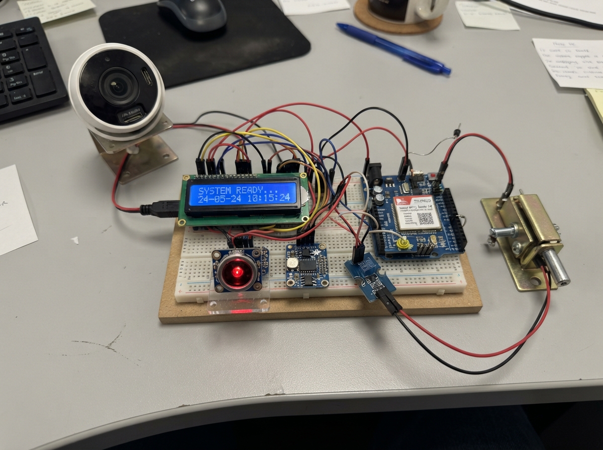
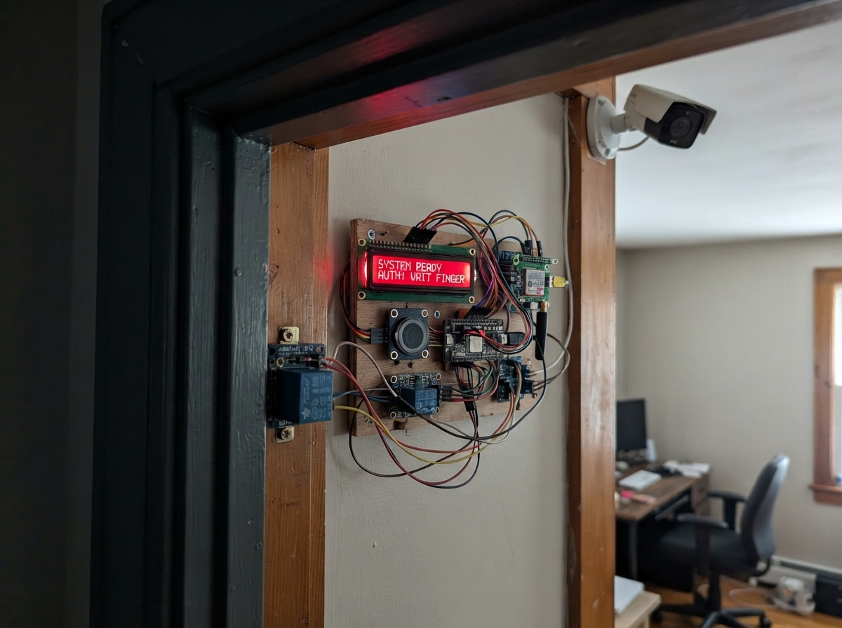
This fingerprint door security system combines biometric access control with remote alerts and video recording. Built around an Arduino Uno, it uses an optical fingerprint sensor for authentication, a solenoid latch for the door lock, a GSM shield to send SMS alerts, and an IP camera with microSD recording to capture all access events with precise timestamps from the RTC module.
The guide provides a complete wiring diagram, parts list, and step-by-step assembly instructions for building a bench prototype with proper power distribution and protection circuits. Firmware is included to manage fingerprint enrollment, lock timing, camera triggers, and SMS notifications—all displayed on the 16x2 LCD screen. Readers will learn how to integrate multiple communication protocols, handle relay switching safely with flyback diodes, and set up maintenance access controls.
Wiring diagram
Gather all the parts
Assemble it in 8 steps
1. Build a bench prototype first
Use a loose door/latch test panel. Put the sensor in a fixed front knob cap or front escutcheon, with its scan window accessible. Keep the rotating handle mechanically independent so wires cannot twist. Put the Uno, shield, relays, LCD connections and key switch in a protected interior enclosure. Mount the camera beside the door with a clear view of visitors.
- This is a prototype, not a certified security lock. Never use it as the sole lock on an occupied exit. Provide mechanical free egress and a manual key override.
2. Prepare separate power branches
Disconnect all power. Connect adapter positive through the 3A fuse to the 12V distribution. Adapter negative is common ground. Connect the buck input to 12V and ground. Before attaching electronics, measure and set its output to 5.0V. The buck feeds peripherals only. Power the Uno separately by its USB connector. Join peripheral ground to Uno GND, but do not join buck positive to Uno 5V.
- Use an enclosed certified adapter. Never handle mains wiring. Never power the lock or GSM shield from the Uno 5V pin. Use screw terminals and suitable wires for lock and supply currents, not solderless breadboard power paths.
3. Connect the fingerprint sensor
Use the original 5V Adafruit 751 slim-connector sensor described in the parts list. VCC goes to peripheral 5V, GND to common ground, TX to D2 (fingerprint data into Uno), and RX to D3 (commands out). Route the cable through the fixed door trim with strain relief.
- Do not substitute the 3.3V-only socket-header version using these power connections. Identify pins by the exact sensor documentation, not wire colors.
4. Wire the screen and clock
LCD VCC and RTC VIN go to peripheral 5V; both GND pins go to common ground. Both SDA pins go to A4 (data), and both SCL pins to A5 (clock). Insert the CR1220 in the RTC holder with correct polarity. Leave SQW, 32K and RST unused. Adjust the LCD contrast screw until letters are visible.
- Coin cells are a swallowing hazard. Secure the holder inside the enclosure.
5. Connect the GSM shield without stacking
Mount the Seeed GPRS Shield V3.0 separately. Select its SWSerial jumpers. Connect its Uno-side TX output to D7 (SMS replies) and RX input to D8 (SMS commands). Connect shield 5V to the peripheral buck output and GND to common ground. Leave all other shield headers unconnected, including A4/A5, D0/D1, VIN and D9. Insert an activated SMS-capable SIM with PIN lock disabled. Attach its antenna.
- This exact shield includes its power regulator and Uno-compatible serial interface; a bare SIM900/SIM800 module is not a drop-in replacement.
- After applying power, hold its power button for about two seconds. Confirm the network LED blinks about once every three seconds. Repeat after a complete power outage.
- SIM900 is 2G-only. It cannot send SMS where 2G GSM service has shut down. This older shield may require sourcing existing stock.
6. Connect the lock relay and protection diode
Relay VCC goes to peripheral 5V, GND to ground, SIG to D5 (unlock control). Connect the 10k pull-down from D5 to ground. Relay COM goes to fused 12V and NO to lock positive. Lock negative goes to ground. Put the 1N4007 directly across the lock: striped end K to lock positive, other end A to lock negative. Both relay terminals are normally-open switch contacts.
- Use a power-to-unlock 12V latch drawing at most 600mA. Reversing the diode shorts the supply when unlocking. Do not connect a solenoid directly to an Uno pin.
7. Connect the independent recording camera
With camera power off, insert the high-endurance microSD. Camera 12V goes to fused 12V and its power ground to common ground. The second Grove relay VCC goes to peripheral 5V, GND to ground, SIG to D6. Fit its 10k pull-down from D6 to ground. Connect only the relay's dry contacts between camera ALARM IN and its alarm GND: NO to ALARM IN and COM to alarm GND. Use the -IS camera version with alarm terminals.
- Never apply 5V or 12V to the camera alarm input. Do not confuse alarm output or audio terminals with alarm input.
8. Protect maintenance access
Connect the interior key switch between D4 and common ground. Closed enables USB setup and disables normal unlocking. Open arms fingerprint monitoring. Keep the switch and the Uno USB port inaccessible from outside. Secure wiring away from latch motion and metal edges. Leave ventilation around the solenoid and power electronics.
- Test with the door open. A fail-secure lock stays locked on power failure; a separate mechanical way out is essential.
Review all connections
1. Connections between "psu" and "Arduino"
2. Connections between "fuse" and "Arduino"
3. Connections between "buck" and "Arduino"
4. Connections between "lcd" and "Arduino"
5. Connections between "rtc" and "Arduino"
6. Connections between "finger" and "Arduino"
7. Connections between "gsm" and "Arduino"
8. Connections between "lockrelay" and "Arduino"
9. Connections between "camrelay" and "Arduino"
10. Connections between "pulllock" and "Arduino"
11. Connections between "pullcam" and "Arduino"
12. Connections between "lock" and "Arduino"
13. Connections between "diode" and "Arduino"
14. Connections between "camera" and "Arduino"
15. Connections between "sd" and "Arduino"
16. Connections between "battery" and "Arduino"
17. Connections between "setupkey" and "Arduino"
Deploy the firmware
#include <Arduino.h>
#include <SPI.h>
#include <Wire.h>
#include <EEPROM.h>
#include <SoftwareSerial.h>
#include <Adafruit_Fingerprint.h>
#include <LiquidCrystal_I2C.h>
#include <RTClib.h>

// Original Adafruit 751 sensor; Seeed SIM900 shield in SWSerial mode.
constexpr uint8_t LOCK=5, CAMERA=6, SETUP_KEY=4;
SoftwareSerial fpPort(2,3), gsmPort(7,8);
Adafruit_Fingerprint finger(&fpPort);
LiquidCrystal_I2C lcd(0x27,16,2);
RTC_DS3231 rtc;
bool sensorOK=false, rtcOK=false, removed=true, unlocked=false, recording=false;
uint32_t lockUntil=0, cameraUntil=0, messageUntil=0, pollAt=0;
uint8_t failures=0;
char phone[20]={0}, command[40];
uint8_t commandLen=0;
bool maintenance=false;
const uint8_t MAGIC=0xB7;

void show(const __FlashStringHelper *a,const __FlashStringHelper *b) {
  lcd.clear(); lcd.setCursor(0,0); lcd.print(a); lcd.setCursor(0,1); lcd.print(b);
}
bool due(uint32_t t) { return (int32_t)(millis()-t)>=0; }
void timers() {
  if(unlocked && due(lockUntil)) { digitalWrite(LOCK,LOW); unlocked=false; }
  if(recording && due(cameraUntil)) { digitalWrite(CAMERA,LOW); recording=false; }
}
void idleScreen() {
  if(!sensorOK) show(F("Sensor fault"),F("Door stays locked"));
  else show(F("Place Fingerprint"),F("BioKnob Ready"));
}
void pauseMs(uint32_t ms) {
  uint32_t start=millis();
  while(millis()-start<ms) { timers(); delay(1); }
}
bool validPhone(const char *p) {
  uint8_t n=strlen(p); if(n<9 || n>18 || p[0]!='+') return false;
  for(uint8_t i=1;i<n;i++) if(p[i]<'0'||p[i]>'9') return false;
  return true;
}
// Streaming parser: bounded buffer and explicit modem errors/timeouts.
bool response(const char *token,uint32_t timeout) {
  char buf[100]={0}; uint8_t n=0; uint32_t start=millis();
  while(millis()-start<timeout) {
    timers();
    while(gsmPort.available()) {
      char c=gsmPort.read();
      if(n==sizeof(buf)-1) { memmove(buf,buf+40,n-40); n-=40; }
      buf[n++]=c; buf[n]=0;
      if(strstr(buf,"ERROR")) return false;
      if(strstr(buf,token)) return true;
    }
  }
  return false;
}
void drainModem() { while(gsmPort.available()) gsmPort.read(); }
bool at(const __FlashStringHelper *s,const char *token="OK",uint32_t ms=3000) {
  drainModem(); gsmPort.println(s); return response(token,ms);
}
bool sms() {
  if(!validPhone(phone)) { Serial.println(F("SMS not sent: set administrator number with N+countrycode...")); return false; }
  gsmPort.listen();
  bool ok=false;
  // Retry wake/autobaud only. Never blindly retry a submitted SMS (duplicates).
  for(uint8_t i=0;i<3 && !ok;i++) ok=at(F("AT"));
  if(!ok || !at(F("ATE0")) || !at(F("AT+CPIN?"),"READY") ||
     !at(F("AT+CMGF=1"))) { fpPort.listen(); return false; }
  drainModem(); gsmPort.print(F("AT+CMGS=\"")); gsmPort.print(phone); gsmPort.println('"');
  if(!response(">",5000)) { gsmPort.write(27); fpPort.listen(); return false; }
  gsmPort.print(F("BioKnob: Unauthorized access attempt detected. Three consecutive failed fingerprints. "));
  if(rtcOK && !rtc.lostPower()) {
    DateTime t=rtc.now(); char stamp[22];
    snprintf(stamp,sizeof(stamp),"%04u-%02u-%02u %02u:%02u:%02u",t.year(),t.month(),t.day(),t.hour(),t.minute(),t.second());
    gsmPort.print(stamp);
  } else gsmPort.print(F("RTC time not set."));
  gsmPort.write(26);
  // +CMGS is network submission acknowledgement, not handset delivery proof.
  ok=response("+CMGS:",60000);
  if(ok) ok=response("OK",5000);
  fpPort.listen(); return ok;
}
void alert() {
  digitalWrite(LOCK,LOW); unlocked=false;
  digitalWrite(CAMERA,HIGH); recording=true; cameraUntil=millis()+30000UL;
  show(F("Unauthorized"),F("Attempt Detected"));
  Serial.println(F("Unauthorized Attempt Detected; camera contact held 30 seconds."));
  pauseMs(1000);
  show(F("Sending SMS..."),F("Door locked"));
  bool sent=sms();
  if(sent) show(F("SMS Alert Sent"),F("Network accepted"));
  else show(F("SMS Alert Failed"),F("Check SIM/setup"));
  Serial.println(sent?F("SMS accepted by network; delivery not confirmed."):F("SMS failed/unconfirmed; no automatic duplicate retry."));
  messageUntil=millis()+3000;
}
// Enrollment uses two scans and requires the interior key throughout.
bool capture(uint8_t slot,bool wantFinger) {
  uint32_t start=millis();
  while(millis()-start<20000UL && digitalRead(SETUP_KEY)==LOW) {
    timers(); uint8_t r=finger.getImage();
    if(!wantFinger && r==FINGERPRINT_NOFINGER) return true;
    if(wantFinger && r==FINGERPRINT_OK) return finger.image2Tz(slot)==FINGERPRINT_OK;
    pauseMs(70);
  }
  return false;
}
void enroll(uint16_t id) {
  digitalWrite(LOCK,LOW); unlocked=false; fpPort.listen();
  if(!sensorOK || id<1 || id>162) { Serial.println(F("Use E1 through E162.")); return; }
  show(F("Enroll: place"),F("new finger"));
  if(!capture(1,true)) { Serial.println(F("First scan failed/timeout.")); return; }
  show(F("Remove finger"),F("then scan again"));
  if(!capture(0,false)) return;
  show(F("Scan same finger"),F("a second time"));
  if(!capture(2,true) || digitalRead(SETUP_KEY)!=LOW) return;
  if(finger.createModel()==FINGERPRINT_OK && finger.storeModel(id)==FINGERPRINT_OK)
    Serial.println(F("Fingerprint enrolled in sensor flash."));
  else Serial.println(F("Enrollment failed: scans differ or storage error."));
  removed=false;
}
void execute() {
  if(digitalRead(SETUP_KEY)!=LOW) { Serial.println(F("Setup key is open; command denied.")); return; }
  if(command[0]=='N' && validPhone(command+1)) {
    strncpy(phone,command+1,sizeof(phone));
    for(uint8_t i=0;i<sizeof(phone);i++) EEPROM.update(2+i,phone[i]);
    Serial.println(F("Administrator number saved."));
  } else if(command[0]=='E') enroll(atoi(command+1));
  else if(command[0]=='T' && strlen(command)==15 && rtcOK) {
    bool digits=true; for(uint8_t i=1;i<15;i++) if(!isDigit(command[i])) digits=false;
    if(digits) {
      char b[5]={0}; memcpy(b,command+1,4); uint16_t y=atoi(b);
      uint8_t v[5]; for(uint8_t i=0;i<5;i++) { b[0]=command[5+i*2];b[1]=command[6+i*2];b[2]=0;v[i]=atoi(b); }
      DateTime d(y,v[0],v[1],v[2],v[3],v[4]);
      if(y>=2026 && y<=2099 && d.isValid()) { rtc.adjust(d); Serial.println(F("RTC set. Set camera to SAME time zone separately.")); }
      else Serial.println(F("Invalid date/time."));
    }
  } else Serial.println(F("Setup: N+countrycodeNumber | E1..E162 | TYYYYMMDDhhmmss"));
  messageUntil=millis()+2000;
}
void usbCommands() {
  while(Serial.available()) {
    char c=Serial.read();
    if(c=='\n' || c=='\r') {
      if(commandLen) { command[commandLen]=0; execute(); commandLen=0; }
    } else if(commandLen<sizeof(command)-1) command[commandLen++]=c;
    else commandLen=0;
  }
}
void setup() {
  digitalWrite(LOCK,LOW); digitalWrite(CAMERA,LOW);
  pinMode(LOCK,OUTPUT);pinMode(CAMERA,OUTPUT);pinMode(SETUP_KEY,INPUT_PULLUP);
  Serial.begin(115200); Wire.begin(); Wire.setWireTimeout(25000,true);
  lcd.init(); lcd.backlight(); show(F("BioKnob starting"),F("Door locked"));
  rtcOK=rtc.begin();
  if(EEPROM.read(0)!=MAGIC) { EEPROM.update(0,MAGIC);EEPROM.update(1,0);EEPROM.update(2,0); }
  failures=min((uint8_t)2,EEPROM.read(1));
  for(uint8_t i=0;i<sizeof(phone);i++) phone[i]=EEPROM.read(2+i);
  phone[sizeof(phone)-1]=0;
  gsmPort.begin(19200); finger.begin(57600);fpPort.listen(); pauseMs(1000);
  sensorOK=finger.verifyPassword();
  Serial.println(F("BioKnob. USB serial 115200, newline. Close interior key for setup."));
  Serial.println(F("N+countrycodeNumber | E1..E162 | TYYYYMMDDhhmmss. Open key to arm."));
  if(!rtcOK || rtc.lostPower()) Serial.println(F("WARNING: RTC unset; set with T command."));
  if(!validPhone(phone)) Serial.println(F("WARNING: SMS recipient not set."));
  idleScreen();
}
void loop() {
  timers(); usbCommands();
  if(messageUntil && due(messageUntil)) { messageUntil=0;idleScreen(); }
  if(digitalRead(SETUP_KEY)==LOW) {
    digitalWrite(LOCK,LOW);unlocked=false;
    if(!maintenance) { show(F("Maintenance mode"),F("USB setup only"));maintenance=true; }
    return;
  }
  if(maintenance) { maintenance=false;messageUntil=0;idleScreen(); }
  if(!sensorOK || unlocked || !due(pollAt)) return;
  pollAt=millis()+120;fpPort.listen();
  uint8_t r=finger.getImage();
  if(r==FINGERPRINT_NOFINGER) { removed=true; return; }
  if(r!=FINGERPRINT_OK || !removed) return;
  removed=false; // require full finger lift before another attempt
  r=finger.image2Tz();
  if(r==FINGERPRINT_OK) r=finger.fingerFastSearch();
  if(r==FINGERPRINT_OK) {
    failures=0;EEPROM.update(1,0);
    digitalWrite(LOCK,HIGH);unlocked=true;lockUntil=millis()+5000;
    show(F("Access Granted"),F("Unlock: 5 sec"));messageUntil=lockUntil;
  } else if(r==FINGERPRINT_NOTFOUND || r==FINGERPRINT_IMAGEMESS || r==FINGERPRINT_FEATUREFAIL || r==FINGERPRINT_INVALIDIMAGE) {
    failures++; EEPROM.update(1,failures);
    show(F("Access Denied"),F("Lift finger")); messageUntil=millis()+2000;
    if(failures>=3) { alert(); failures=0; EEPROM.update(1,0); }
  } else { show(F("Sensor error"),F("Try again"));messageUntil=millis()+2000; }
}
Remix this project
Make it yours in one click
Open a full copy of this project in your own Schematik workspace, diagram, code, parts, and assembly steps included. Swap the sensor, add features, or redesign the whole thing with AI. The author's original stays untouched.