Community project
Arduino Reaction-Time Game
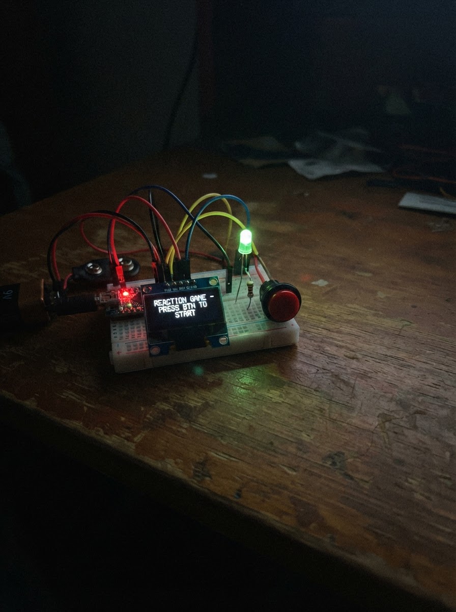
Build a reaction-time game that tests how quickly a player can respond to a visual cue. The Arduino Uno monitors a push button and controls an LED to create a game loop: after a random delay, the LED lights up, and the player must press the button as fast as possible. The Arduino measures the reaction time and provides visual feedback through LED blinks.
This guide includes a complete wiring diagram showing how to connect the LED and resistor to the Uno's output pin, wire the push button to the input pin, and connect the 9V barrel-jack adapter for power. Assembly takes just a few minutes on a breadboard, and the included firmware handles debouncing, random delays, and reaction timing. Once deployed, the game is ready to play immediately.
Wiring diagram

Gather all the parts
Assemble it in 5 steps
1. Prepare the Uno and breadboard
Unplug all power before wiring. Place the Arduino Uno beside the breadboard and choose a breadboard rail as ground.
- The 9 V adapter will power the Uno; USB is not required for normal operation.
- Never change wiring while the wall adapter or USB cable is connected.
2. Wire the red reaction LED
Connect Arduino D13 to one end of the 220 Ω resistor. Connect the resistor's other end to the red LED anode (longer lead). Connect the LED cathode (shorter lead and usually the flat side of the case) to Uno GND.
- The resistor has no polarity.
- The Uno's built-in D13 LED may also light, but the external LED is the game cue.
- Never connect the LED directly between D13 and GND without the 220 Ω resistor.
3. Wire the reaction button
Fit the momentary button across the breadboard center gap so its two switch sides are separate. Connect one switch side to Arduino D2 and the opposite side to Uno GND.
- The code uses the Uno's internal pull-up resistor, so no external resistor is needed.
- A button press reads LOW because it connects D2 to ground.
- On four-leg tactile buttons, the two legs on each same side are already connected; use one leg from each opposite side.
4. Connect the wall adapter
Use only a regulated 9 V DC, center-positive adapter with a 5.5 mm × 2.1 mm barrel plug. Insert its plug directly into the Arduino Uno DC barrel jack; the adapter center pin is +9 V and sleeve is ground.
- The Uno onboard regulator supplies the board from this jack.
- Do not connect the adapter's 9 V output to the Uno 5V pin.
- Confirm the adapter output is 9 V DC and center-positive before plugging it in. Do not use an unregulated adapter, a higher-voltage supply, or a damaged cable.
5. Deploy and play
With the wall adapter powering the Uno, use Schematik’s Deploy button to load the project. View its Serial output at 115200 baud. Release the button, wait through the random delay, then press only when the LED lights.
- After a valid reaction time, the LED blinks three times before the next round.
- An early press is reported as a false start.
- Keep the button released while a new round arms.
Review all connections
1. Connections between "led_resistor" and "Arduino"
2. Connections between "red_led" and "Arduino"
3. Connections between "reaction_button" and "Arduino"
4. Connections between "wall_adapter" and "Arduino"
Deploy the firmware
#include <Arduino.h>

enum GameState {
  WAIT_FOR_RELEASE,
  WAIT_RANDOM_DELAY,
  WAIT_FOR_REACTION,
  SHOW_RESULT
};

bool buttonPressedEvent();
bool buttonIsReleased();
void blinkResultLed();
void startWaitingRound();

const uint8_t LED_PIN = 13;
const uint8_t BUTTON_PIN = 2;
const unsigned long DEBOUNCE_MS = 30;
const unsigned long BLINK_MS = 180;

GameState state = WAIT_FOR_RELEASE;
unsigned long stateStartedAt = 0;
unsigned long cueStartedAt = 0;
unsigned long randomDelayMs = 0;

bool rawLastReading = HIGH;
bool stableButtonState = HIGH;
unsigned long lastRawChangeAt = 0;

bool buttonPressedEvent() {
  const bool reading = digitalRead(BUTTON_PIN);
  const unsigned long now = millis();

  if (reading != rawLastReading) {
    rawLastReading = reading;
    lastRawChangeAt = now;
  }

  if ((now - lastRawChangeAt) >= DEBOUNCE_MS && reading != stableButtonState) {
    stableButtonState = reading;
    return stableButtonState == LOW;
  }

  return false;
}

bool buttonIsReleased() {
  return stableButtonState == HIGH;
}

void blinkResultLed() {
  for (uint8_t blink = 0; blink < 3; ++blink) {
    digitalWrite(LED_PIN, HIGH);
    delay(BLINK_MS);
    digitalWrite(LED_PIN, LOW);
    delay(BLINK_MS);
  }
}

void startWaitingRound() {
  digitalWrite(LED_PIN, LOW);
  randomDelayMs = random(1500, 5001);
  stateStartedAt = millis();
  state = WAIT_RANDOM_DELAY;
  Serial.println(F("Get ready..."));
}

void setup() {
  pinMode(LED_PIN, OUTPUT);
  pinMode(BUTTON_PIN, INPUT_PULLUP);
  digitalWrite(LED_PIN, LOW);

  Serial.begin(115200);
  randomSeed(analogRead(A0) ^ micros());
  Serial.println(F("Reaction-time game ready. Release the button to begin."));
}

void loop() {
  const unsigned long now = millis();
  const bool pressed = buttonPressedEvent();

  switch (state) {
    case WAIT_FOR_RELEASE:
      digitalWrite(LED_PIN, LOW);
      if (buttonIsReleased()) {
        startWaitingRound();
      }
      break;

    case WAIT_RANDOM_DELAY:
      if (pressed) {
        Serial.println(F("False start! Wait for the LED."));
        state = WAIT_FOR_RELEASE;
      } else if (now - stateStartedAt >= randomDelayMs) {
        digitalWrite(LED_PIN, HIGH);
        cueStartedAt = now;
        state = WAIT_FOR_REACTION;
        Serial.println(F("GO!"));
      }
      break;

    case WAIT_FOR_REACTION:
      if (pressed) {
        const unsigned long reactionMs = now - cueStartedAt;
        digitalWrite(LED_PIN, LOW);
        Serial.print(F("Reaction time: "));
        Serial.print(reactionMs);
        Serial.println(F(" ms"));
        state = SHOW_RESULT;
      }
      break;

    case SHOW_RESULT:
      blinkResultLed();
      Serial.println(F("Release the button for the next round."));
      state = WAIT_FOR_RELEASE;
      break;
  }
}
Remix this project
Make it yours in one click
Open a full copy of this project in your own Schematik workspace — diagram, code, parts, and assembly steps included. Swap the sensor, add features, or redesign the whole thing with AI. The author's original stays untouched.