Community project
Assistive Vision Smart Glasses
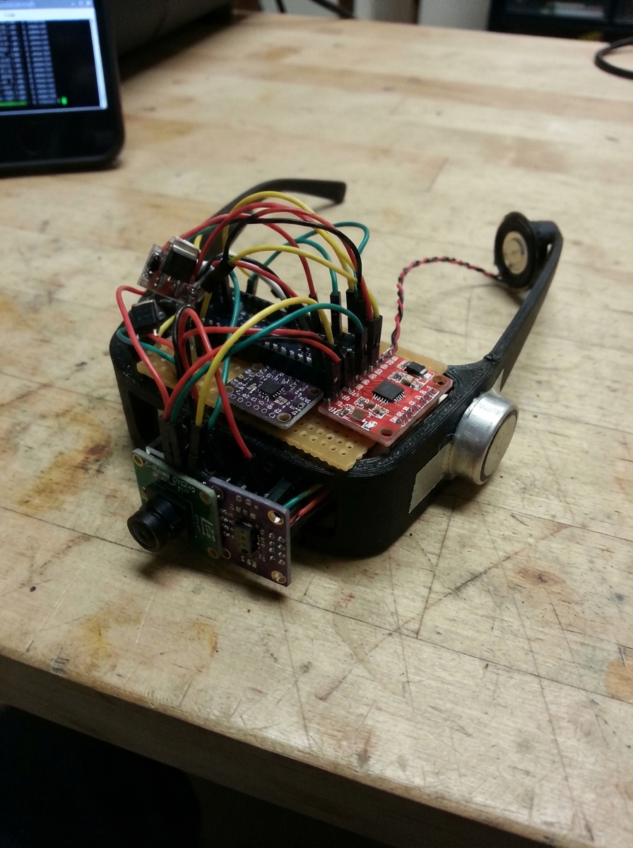
These smart glasses combine computer vision, spatial awareness, and audio feedback to assist users with navigation and object detection. Built around an ESP32-S3 microcontroller, the system integrates a 2MP camera for visual input, an 8×8 time-of-flight sensor for precise distance mapping, a 6-axis IMU for head orientation tracking, and audio/haptic feedback channels for non-visual alerts.
This guide provides a complete wiring diagram, full parts list, and step-by-step assembly instructions starting with the power delivery system and progressing through sensor integration and firmware bring-up. Builders will learn how to wire a LiPo charging circuit with protection, connect multiple I2C sensors, configure audio amplification, and implement haptic feedback—all the essentials for a wearable assistive device.
Wiring diagram
Gather all the parts
Assemble it in 5 steps
1. Build the power section first
Place the USB-C receptacle, BQ24074 charger, battery-protection circuit, TPS63070 regulator, and JST-GH battery connector together at one board end. Keep the charger and regulator capacitor loops as short as their datasheets require; the 3.3 V rail must not touch USB 5 V directly.
- Put the USB ESD part directly behind the USB-C connector.
- Use a protected 1-cell LiPo with an NTC lead that matches the charger temperature input.
- Do not plug in a battery until a meter confirms there is no short from the protected battery positive wire to ground; a shorted LiPo can overheat or catch fire.
- Do not connect USB 5 V to the 3.3 V rail; doing so can damage every 3.3 V part.
2. Fit the ESP32-S3 and camera connector
Place the ESP32-S3-WROOM-1-N8R8 module so its antenna end faces the board edge and has no copper, battery, connector, or metal directly under or in front of it. Put the 20-pin OV2640 connector close to GPIO4 through GPIO17 and route the eight data wires, PCLK, HREF, VSYNC, and XCLK as one short, equal-style group.
- Keep a solid ground plane below the camera routing and avoid vias in the pixel-clock route where possible.
- GPIO35, GPIO36, and GPIO37 belong to the module's PSRAM and must not be routed to connectors.
- Do not place copper or the LiPo battery in the antenna keep-out area; this can severely reduce wireless range.
3. Connect the distance and motion sensors
Connect the VL53L5CX carrier and the MPU-6050 to the 3.3 V rail and ground. Join their SDA wires on GPIO1 and their SCL wires on GPIO2, then fit only the planned 4.7 kΩ pull-ups on the main PCB. Connect LiDAR INT to GPIO18 and IMU INT to GPIO21; tie MPU-6050 AD0 to ground so it uses address 0x68.
- Before fitting a sensor breakout with its own pull-ups, check its schematic and remove or disable duplicate pull-ups if the total pull-up resistance would be too low.
- The Pololu carrier must be powered from 3.3 V in this design because its I2C high level follows VIN; powering it at 5 V can send 5 V logic into the ESP32.
4. Wire audio and haptics
Connect the MAX98357A to 3.3 V and ground, then connect BCLK to GPIO38, LRC to GPIO39, DIN to GPIO40, and SD to GPIO41. Connect the two speaker wires only to SPK+ and SPK-. Feed the motor from 3.3 V and route its negative wire through the AO3400A drain; fit the SS14 across the motor with its striped cathode at motor positive, use the 100 Ω gate resistor from GPIO42, and fit the 100 kΩ gate-to-ground resistor.
- Keep the motor loop away from the IMU and camera connector because the motor creates electrical noise.
- Use an 8 ohm, 1 W or higher open-ear transducer.
- Never connect either MAX98357A speaker terminal to ground; its two output wires both switch and grounding either can damage the amplifier.
5. Add monitoring and bring-up points
Fit the 1.0 MΩ and 330 kΩ battery divider between protected battery positive, GPIO3, and ground. Add labeled pads for VBAT, USB5V, 3V3, GND, SDA, SCL, EN, GPIO0, UART0 TX, and UART0 RX. Fit four mounting holes and inspect every connector label before power-up.
- Use a high-impedance meter when checking the battery divider; it should be about one quarter of the protected battery voltage at GPIO3.
- Use a four-layer board with an uninterrupted inner ground plane; separate the buck-boost switching loop from camera and sensor traces.
- Do not use this prototype as a mobility or medical safety device until it has been independently tested in the intended enclosure and environment.
Review all connections
1. Connections between "camera_ov2640" and "ESP32"
2. Connections between "lidar_vl53l5cx" and "ESP32"
3. Connections between "imu_mpu6050" and "ESP32"
4. Connections between "amp_max98357a" and "ESP32"
5. Connections between "motor" and "ESP32"
6. Connections between "motor_mosfet" and "ESP32"
7. Connections between "flyback_diode" and "ESP32"
8. Connections between "usb_c" and "ESP32"
9. Connections between "usb_esd" and "ESP32"
10. Connections between "r_cc1" and "ESP32"
11. Connections between "r_cc2" and "ESP32"
12. Connections between "charger_bq24074" and "ESP32"
13. Connections between "battery_jst" and "ESP32"
14. Connections between "battery_protection" and "ESP32"
15. Connections between "reg_tps63070" and "ESP32"
16. Connections between "r_gate" and "ESP32"
17. Connections between "r_gate_pd" and "ESP32"
18. Connections between "r_bat_top" and "ESP32"
19. Connections between "r_bat_bottom" and "ESP32"
20. Connections between "r_i2c_sda" and "ESP32"
21. Connections between "r_i2c_scl" and "ESP32"
Deploy the firmware
#include <Arduino.h>
#include <Wire.h>

constexpr int I2C_SDA_PIN = 1;
constexpr int I2C_SCL_PIN = 2;
constexpr int LIDAR_INT_PIN = 18;
constexpr int IMU_INT_PIN = 21;
constexpr int BATTERY_ADC_PIN = 3;
constexpr int AMP_SD_PIN = 41;
constexpr int MOTOR_PIN = 42;

uint32_t lastReportMs = 0;

void setup() {
  Serial.begin(115200);
  delay(200);

  pinMode(AMP_SD_PIN, OUTPUT);
  digitalWrite(AMP_SD_PIN, LOW);  // Keep the speaker quiet during board bring-up.
  pinMode(MOTOR_PIN, OUTPUT);
  digitalWrite(MOTOR_PIN, LOW);   // Keep the motor off during board bring-up.

  pinMode(LIDAR_INT_PIN, INPUT);
  pinMode(IMU_INT_PIN, INPUT);
  analogReadResolution(12);
  Wire.begin(I2C_SDA_PIN, I2C_SCL_PIN, 400000);

  Serial.println("DUNE VISION Ω hardware bring-up");
}

void loop() {
  const uint32_t now = millis();
  if (now - lastReportMs >= 1000) {
    lastReportMs = now;
    const uint16_t rawBattery = analogRead(BATTERY_ADC_PIN);
    const float adcVoltage = (3.3f * rawBattery) / 4095.0f;
    const float batteryVoltage = adcVoltage * ((1000000.0f + 330000.0f) / 330000.0f);

    Serial.print("Battery divider estimate: ");
    Serial.print(batteryVoltage, 2);
    Serial.println(" V");
  }
  delay(10);
}
Remix this project
Make it yours in one click
Open a full copy of this project in your own Schematik workspace, diagram, code, parts, and assembly steps included. Swap the sensor, add features, or redesign the whole thing with AI. The author's original stays untouched.