Community project
ESP32 CubeSat Telemetry Dashboard
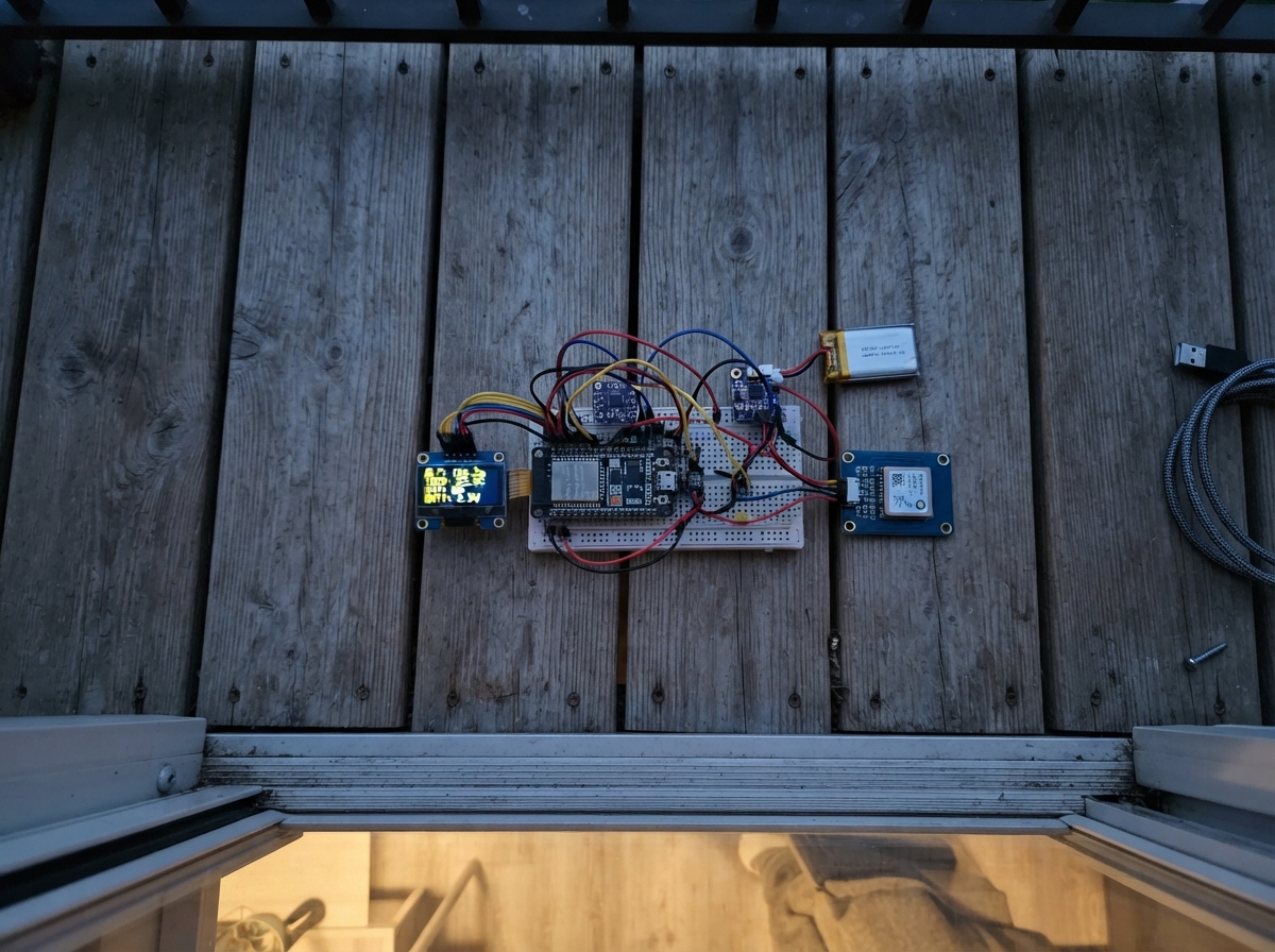
This project builds a compact telemetry dashboard for the ESP32 that collects and displays real-time sensor data from an inertial measurement unit, barometric pressure sensor, and GPS receiver. The 128x64 OLED screen shows live readings of acceleration, rotation, altitude, temperature, and location, while a web interface streams the data as JSON for remote monitoring.
The guide provides a complete wiring diagram for connecting the SSD1306 display, MPU-6500/9250 IMU, BMP280/BME280 barometer, and NEO-6M GPS module to the ESP32, along with the firmware needed to initialize all sensors, compute orientation angles, and serve telemetry over WiFi. Assembly takes about 20 minutes and requires only basic soldering skills.
Wiring diagram
Gather all the parts
Assemble it in 6 steps
1. Start with USB unplugged
Use an ESP32 DevKit v1 and short jumper wires. This is a USB-powered tabletop prototype. Keep all module power at 3.3V and share ground.
- Never apply 5V to these signal pins. This project is not suitable for flight or space.
2. Connect the seven-pin screen
OLED GND → GND; VCC → 3V3; D0 (sometimes printed DO) → GPIO18 (clock); D1 → GPIO23 (data); RES → GPIO26 (reset); DC → GPIO27 (data or command); CS → GPIO25 (screen select). The chosen screen is SSD1306 128×64 SPI.
- Seven pins alone do not identify the controller. A different controller needs a firmware change.
3. Connect the motion module
VCC → 3V3; GND → GND; SDA → GPIO21 (data); SCL → GPIO22 (clock); AD0 (ADO) → GND (address); NCS → 3V3 (I2C mode); FSYNC → GND. Leave EDA, ECL and INT unconnected. Secure the sensor flat with its marked axes visible.
4. Connect the pressure module
HW-611 VCC → 3V3; GND → GND; SDA → GPIO21; SCL → GPIO22; CSB → 3V3 (I2C mode); SDO (SD0) → GND (address 0x76). Shared data and clock wires are intentional. Keep the pressure vent unobstructed.
5. Connect GPS and position the antenna
GPS VCC → 3V3; GND → GND; TX → GPIO32 (GPS data into ESP32). Leave GPS RX unconnected. Attach its supplied antenna and face its ceramic side toward open sky.
- Allow several minutes outdoors for the first fix. Indoor location may never appear.
- Some regulator-equipped GPS breakouts cannot run reliably from 3.3V at their header. Do not change to 5V without verifying that the breakout accepts it.
6. Check before powering
Check every connection against pin labels rather than pin order. Keep wires short and insulate the boards from a metal CubeSat frame. Start with a stable USB supply and leave the sensors ventilated.
Review all connections
1. Connections between "oled" and "ESP32"
2. Connections between "imu" and "ESP32"
3. Connections between "baro" and "ESP32"
4. Connections between "gps" and "ESP32"
Deploy the firmware
#include <Arduino.h>
#include <Wire.h>
#include <SPI.h>
#include <WiFi.h>
#include <WebServer.h>
#include <DNSServer.h>
#include <Adafruit_SSD1306.h>
#include <Adafruit_BMP280.h>
#include <Adafruit_BME280.h>
#include <TinyGPS++.h>
#include <math.h>
#include "dashboard.h"
Adafruit_SSD1306 oled(128,64,&SPI,27,26,25);
Adafruit_BMP280 bmp;
Adafruit_BME280 bme;
TinyGPSPlus gps;
WebServer server(80);
DNSServer dns;
const IPAddress apIP(192,168,4,1);
bool screen=false,imu=false,baro=false,isBme=false;
float ax=NAN,ay=NAN,az=NAN,gx=NAN,gy=NAN,gz=NAN,roll=NAN,pitch=NAN,temp=NAN,pressure=NAN,humidity=NAN;
uint32_t imuStamp=0,lastSample=0,lastEnv=0,lastDraw=0;
uint32_t introStarted=0;
int readReg(uint8_t a,uint8_t r){Wire.beginTransmission(a);Wire.write(r);if(Wire.endTransmission(false))return -1;if(Wire.requestFrom(a,(uint8_t)1)!=1)return -1;return Wire.read();}
void writeReg(uint8_t r,uint8_t v){Wire.beginTransmission(0x68);Wire.write(r);Wire.write(v);Wire.endTransmission();}
String num(double n,int digits=2){return isfinite(n)?String(n,digits):String("null");}
bool fix(){return gps.location.isValid()&&gps.location.age()<3000;}
String telemetry(){
 String s="{\"uptime\":"+String(millis()/1000)+",\"imu\":"+String(imu&&millis()-imuStamp<1000?"true":"false")+",\"baro\":"+String(baro?"true":"false")+",\"fix\":"+String(fix()?"true":"false");
 const char* names[]={"ax","ay","az","gx","gy","gz","roll","pitch","temp","pressure","humidity"};
 float vals[]={ax,ay,az,gx,gy,gz,roll,pitch,temp,pressure,humidity};
 for(int i=0;i<11;i++)s+=",\""+String(names[i])+"\":"+num(vals[i]);
 s+=",\"lat\":"+num(fix()?gps.location.lat():NAN,6)+",\"lon\":"+num(fix()?gps.location.lng():NAN,6);
 s+=",\"alt\":"+num(fix()&&gps.altitude.isValid()&&gps.altitude.age()<3000?gps.altitude.meters():NAN);
 s+=",\"speed\":"+num(fix()&&gps.speed.isValid()&&gps.speed.age()<3000?gps.speed.kmph():NAN);
 s+=",\"sats\":"+String(gps.satellites.isValid()&&gps.satellites.age()<5000?gps.satellites.value():0)+",\"gpsChars\":"+String(gps.charsProcessed())+"}";return s;
}
void setup(){
 Serial.begin(115200);Wire.begin(21,22);Wire.setTimeOut(30);SPI.begin(18,19,23,25);
 screen=oled.begin(SSD1306_SWITCHCAPVCC);
 if(screen){
  oled.clearDisplay();oled.setTextColor(SSD1306_WHITE);
  oled.setTextSize(2);oled.setCursor(22,4);oled.print("CUBESAT");
  oled.setTextSize(1);oled.setCursor(19,28);oled.print("MISSION CONTROL");
  oled.setCursor(10,44);oled.print("Starting sensors...");
  oled.setCursor(13,56);oled.print("Live data shortly");
  oled.display();introStarted=millis();
 }
 Serial2.begin(9600,SERIAL_8N1,32,-1);
 int id=readReg(0x68,0x75);imu=id==0x70||id==0x71||id==0x73;
 if(imu){writeReg(0x6B,0x80);delay(100);writeReg(0x6B,1);writeReg(0x6C,0);writeReg(0x1B,0);writeReg(0x1C,0);writeReg(0x1A,3);delay(100);}
 int bid=readReg(0x76,0xD0);isBme=bid==0x60;
 if(isBme)baro=bme.begin(0x76);else if(bid==0x58)baro=bmp.begin(0x76);
 WiFi.persistent(false);
 WiFi.mode(WIFI_AP);
 WiFi.setSleep(false);
 bool configured=WiFi.softAPConfig(apIP,apIP,IPAddress(255,255,255,0));
 bool started=WiFi.softAP("CubeSat-Lab","cubesat2026",1,false,4);
 Serial.printf("Wi-Fi AP: %s; address configuration: %s\n",started?"started":"FAILED",configured?"OK":"FAILED");
 Serial.print("AP address: ");Serial.println(WiFi.softAPIP());
 dns.start(53,"*",apIP);
 server.on("/",[]{server.sendHeader("Cache-Control","no-store");server.send_P(200,"text/html; charset=utf-8",DASHBOARD);});
 server.on("/api/telemetry",[]{server.sendHeader("Cache-Control","no-store");server.send(200,"application/json",telemetry());});
 // Phone network-check URLs lead to the local dashboard, not the internet.
 server.onNotFound([]{
  server.sendHeader("Location","http://192.168.4.1/",true);
  server.sendHeader("Cache-Control","no-store");
  server.send(302,"text/plain","Open http://192.168.4.1/");
 });
 server.begin();
 Serial.println("CubeSat-Lab / cubesat2026 / http://192.168.4.1");
}
void loop(){
 while(Serial2.available())gps.encode(Serial2.read());dns.processNextRequest();server.handleClient();uint32_t now=millis();
 if(now-lastSample>=10){lastSample=now;
 if(imu){Wire.beginTransmission(0x68);Wire.write(0x3B);bool ok=Wire.endTransmission(false)==0;
 if(ok&&Wire.requestFrom((uint8_t)0x68,(uint8_t)14)==14){int16_t v[7];for(int i=0;i<7;i++)v[i]=(int16_t)((Wire.read()<<8)|Wire.read());
 ax=v[0]/16384.0;ay=v[1]/16384.0;az=v[2]/16384.0;gx=v[4]/131.0;gy=v[5]/131.0;gz=v[6]/131.0;
 float ar=atan2(ay,az)*180/PI,ap=atan2(-ax,sqrt(ay*ay+az*az))*180/PI;
 float dt=(now-imuStamp)*0.001f;
 if(!isfinite(roll)||dt>0.1f){roll=ar;pitch=ap;}
 else {float predicted=roll+gx*dt;float error=ar-predicted;while(error>180)error-=360;while(error< -180)error+=360;
 float weight=dt/(0.35f+dt);float magnitude=sqrt(ax*ax+ay*ay+az*az);if(fabs(magnitude-1)>0.15f)weight=0;
 roll=predicted+weight*error;while(roll>180)roll-=360;while(roll< -180)roll+=360;
 pitch=(1-weight)*(pitch+gy*dt)+weight*ap;}imuStamp=now;
 }else{ax=ay=az=gx=gy=gz=roll=pitch=NAN;}}
 }
 if(now-lastEnv>=1000){lastEnv=now;if(baro){temp=isBme?bme.readTemperature():bmp.readTemperature();pressure=(isBme?bme.readPressure():bmp.readPressure())/100;humidity=isBme?bme.readHumidity():NAN;}}
 if(screen&&now-introStarted>=3000&&now-lastDraw>=100){lastDraw=now;String text="CubeSat 192.168.4.1\n";
 text+="R:"+(isfinite(roll)?String(roll,0):String("--"))+" P:"+(isfinite(pitch)?String(pitch,0):String("--"))+" deg\n";
 text+="T:"+(isfinite(temp)?String(temp,1):String("--"))+" C\n";
 text+="P:"+(isfinite(pressure)?String(pressure,1):String("--"))+" hPa\n";
 text+=fix()?String(gps.location.lat(),4)+"\n"+String(gps.location.lng(),4):String("GPS: waiting for fix\nSats: ")+String(gps.satellites.value());
 static String old;if(text!=old){old=text;oled.clearDisplay();oled.setTextSize(1);oled.setTextColor(SSD1306_WHITE);oled.setCursor(0,0);oled.print(text);oled.display();}}
 delay(1);
}
Remix this project
Make it yours in one click
Open a full copy of this project in your own Schematik workspace, diagram, code, parts, and assembly steps included. Swap the sensor, add features, or redesign the whole thing with AI. The author's original stays untouched.