Community project
Asthma Hazard Monitoring Node
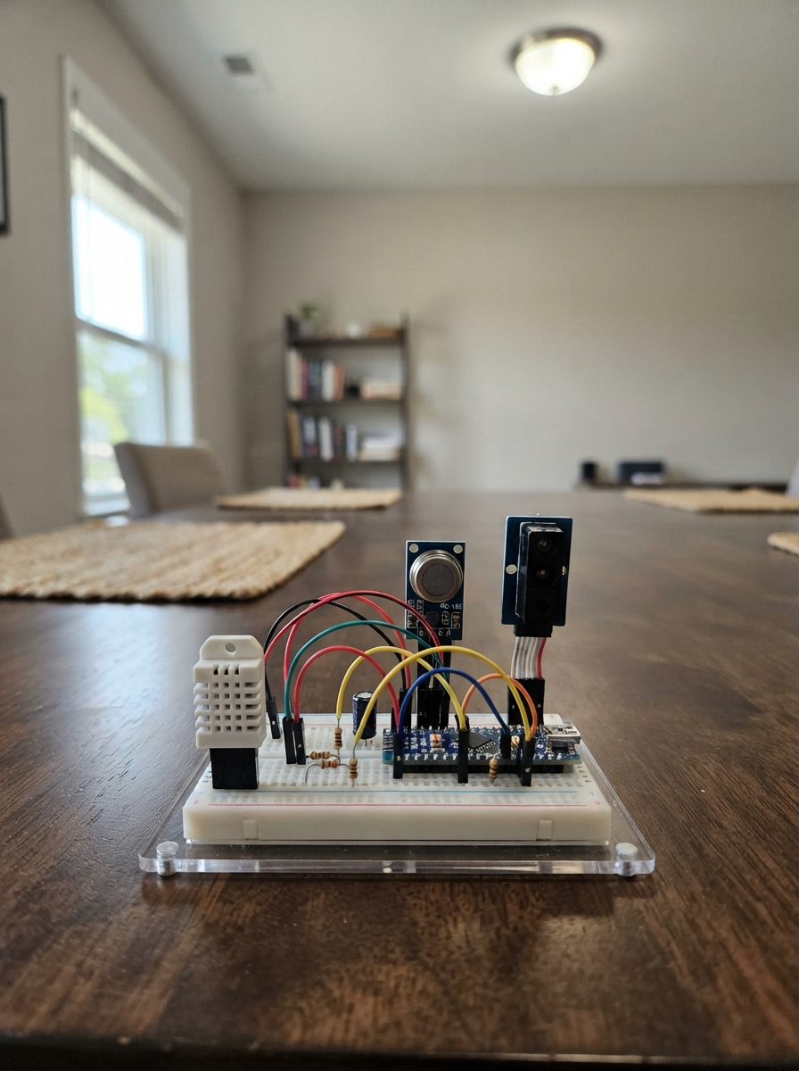
This guide builds an air-quality monitoring node that tracks asthma hazard indicators in indoor or outdoor environments. The ESP32 collects temperature and humidity from a DHT22, measures air-quality compounds with an MQ-135 gas sensor, and quantifies particulate matter using a Sharp optical dust sensor. The node processes these readings into an asthma hazard index and serves the data over Wi-Fi.
You'll receive a complete wiring diagram showing the analog signal conditioning required for each sensor, a full parts list with resistor and capacitor values, and step-by-step assembly instructions including power-rail setup and pre-closure verification. The included firmware handles sensor calibration, Wi-Fi access-point mode, and real-time telemetry updates via a web interface.
Wiring diagram

Gather all the parts
Assemble it in 7 steps
1. Make separate 5 V, 3.3 V, and ground rails
With USB unplugged, connect ESP32 GND to the breadboard ground rail and ESP32 VIN/5V to the 5 V rail. Run a separate short rail from ESP32 3V3 for the DHT22. All sensor ground connections share the ground rail, but only the DHT22 VCC uses the 3.3 V rail.
- Use different wire colors: red for 5 V, orange for 3.3 V, and black for ground.
- Never connect the 5 V rail to ESP32 3V3 or to any ESP32 GPIO — 5 V there can permanently damage the board.
2. Wire the DHT22
Using the pin labels on your exact bare DHT22, connect VCC to 3V3 (power), GND to GND (ground), and DATA to GPIO18 (signal). Put the 4.7 kΩ resistor between DATA and 3V3 (it keeps the data wire in its resting high state).
- Keep the DHT22 physically above and away from the warm MQ-135 heater.
- Confirm the DHT22 pin order from the flat face and markings on your part before applying power — different package views are easy to reverse.
3. Wire the MQ-135 with its protective analog divider
Connect MQ-135 VCC to 5V (heater power) and GND to GND (ground). Connect MQ-135 AO to one end of the 20 kΩ resistor. Join the resistor’s other end to GPIO34 (signal) and to one end of the 10 kΩ resistor; connect the free end of the 10 kΩ resistor to GND (ground). Leave DO unconnected.
- GPIO34 is an ADC1 input, so it continues to read while Wi-Fi is active.
- Do not connect AO directly to GPIO34. MQ-135 modules run from 5 V, and their AO output is not guaranteed to remain within the ESP32’s 3.3 V input limit. The divider protects the ESP32.
4. Wire the Sharp sensor’s single LED supply node
On the six-pin GP2Y1010AU0F connector, connect VCC to 5V (sensor power), S-GND to GND (signal ground), and LED-GND to GND (LED ground). Connect 5V to one end of the 150 Ω resistor; join its other end to the single V-LED pin and to the positive lead of the 220 µF capacitor. Connect the capacitor’s striped negative lead to GND (ground).
- Keep the 150 Ω resistor and 220 µF capacitor close to the Sharp connector. There is one V-LED terminal only; the resistor and capacitor meet at that same point.
- The capacitor’s striped negative lead must go to GND. Reversing it can make it overheat or burst.
- Use the actual six-pin sensor labels or its datasheet pin diagram; do not add a seventh wire or duplicate V-LED connection.
5. Wire the dust reading divider
Connect the Sharp sensor VO pin to one end of the 20 kΩ resistor. Join its other end to GPIO35 (signal) and to one end of the 10 kΩ resistor. Connect the free end of the 10 kΩ resistor to GND (ground).
- This divider reduces the maximum roughly 3.5 V VO signal to about 1.17 V at GPIO35.
- Do not connect VO directly to GPIO35 because the sensor output can exceed the ESP32’s 3.3 V input limit.
6. Connect the Sharp pulse wire directly
Connect the GP2Y1010AU0F LED control pin directly to ESP32 GPIO27 (signal). Do not install a transistor, base resistor, pull-down resistor, or 5 V pull-up resistor on this wire. The firmware drives this active-low input low for 0.32 ms and high for 9.68 ms.
- This is the sixth and final connection to the Sharp sensor connector. GPIO27 is only connected to the LED control terminal, never to 5 V.
- Before connecting GPIO27, verify that this is the sensor’s LED control terminal, not V-LED or LED-GND. Connecting 5 V to GPIO27 can damage the ESP32.
7. Check power before closing the enclosure
Plug the ESP32 into USB and check that its power light and the MQ-135 module light come on. After about two minutes, carefully touch the MQ-135 metal mesh; it should feel slightly warm because its heater runs from 5 V. Keep the MQ-135 low in the enclosure and the DHT22 and Sharp sensor higher, with lower inlet holes and upper outlet holes for passive convection.
- The node uses natural rising warm air only; do not add a fan, motor, pump, or motor driver.
- Allow the MQ-135 to warm up and calibrate against a known clean-air baseline before treating the hazard index as meaningful.
- Do not touch bare wiring while rearranging the breadboard with USB connected. If anything becomes hot apart from the MQ-135 mesh, unplug USB immediately and recheck the rails.
Review all connections
1. Connections between "dht22_1" and "ESP32"
2. Connections between "r_dht_pullup" and "ESP32"
3. Connections between "mq135_1" and "ESP32"
4. Connections between "r_mq_top" and "ESP32"
5. Connections between "r_mq_bottom" and "ESP32"
6. Connections between "gp2y1010_1" and "ESP32"
7. Connections between "r_dust_top" and "ESP32"
8. Connections between "r_dust_bottom" and "ESP32"
9. Connections between "r_gp_led" and "ESP32"
10. Connections between "c_gp_led" and "ESP32"
Deploy the firmware
#include <Arduino.h>
#include <WiFi.h>
#include <WebServer.h>
#include <DHT.h>

constexpr uint8_t DHT_PIN = 18;
constexpr uint8_t DUST_LED_PULSE_PIN = 27;
constexpr uint8_t MQ135_ADC_PIN = 34;
constexpr uint8_t DUST_ADC_PIN = 35;
constexpr uint8_t DHT_TYPE = DHT22;

// Change these before deployment if this node must join an existing Wi-Fi network.
constexpr char AP_SSID[] = "NAFAS-Node";
constexpr char AP_PASSWORD[] = "nafasnode2026";

// Calibration coefficients: replace after comparison with calibrated reference instruments.
constexpr float MQ135_CLEAN_AIR_RAW = 1200.0f;
constexpr float DUST_ZERO_RAW = 0.0f;
constexpr float DUST_RAW_PER_UG_M3 = 8.0f;

DHT dht(DHT_PIN, DHT_TYPE);
WebServer server(80);

float temperatureC = NAN;
float humidityPct = NAN;
uint16_t mq135Raw = 0;
uint16_t dustRaw = 0;
float estimatedPm25 = NAN;
float asthmaHazardIndex = NAN;
uint32_t lastClimateReadMs = 0;
uint32_t lastTelemetryMs = 0;

float clampValue(float value, float low, float high) {
  return value < low ? low : (value > high ? high : value);
}

uint16_t readDustRaw() {
  // The Sharp LED input is active-low. GPIO27 drives it low for the LED pulse.
  digitalWrite(DUST_LED_PULSE_PIN, LOW);
  delayMicroseconds(280);  // Sharp-recommended sample point after LED turn-on.
  const uint16_t reading = analogRead(DUST_ADC_PIN);
  delayMicroseconds(40);   // Completes the required 0.32 ms LED-on pulse.
  digitalWrite(DUST_LED_PULSE_PIN, HIGH);
  delayMicroseconds(9680); // Total period: 10 ms (100 Hz).
  return reading;
}

void updateReadings() {
  mq135Raw = analogRead(MQ135_ADC_PIN);
  dustRaw = readDustRaw();
  estimatedPm25 = fmaxf(0.0f, (static_cast<float>(dustRaw) - DUST_ZERO_RAW) / DUST_RAW_PER_UG_M3);

  const uint32_t now = millis();
  if (now - lastClimateReadMs >= 2000 || lastClimateReadMs == 0) {
    const float newHumidity = dht.readHumidity();
    const float newTemperature = dht.readTemperature();
    if (!isnan(newHumidity)) humidityPct = newHumidity;
    if (!isnan(newTemperature)) temperatureC = newTemperature;
    lastClimateReadMs = now;
  }

  // Transparent preliminary index: PM2.5 is dominant; gas and climate add bounded modifiers.
  const float particulateScore = clampValue(estimatedPm25 * 1.25f, 0.0f, 70.0f);
  const float gasScore = clampValue((static_cast<float>(mq135Raw) - MQ135_CLEAN_AIR_RAW) / 35.0f, 0.0f, 20.0f);
  const float humidityScore = isnan(humidityPct) ? 0.0f : clampValue(fabsf(humidityPct - 50.0f) * 0.20f, 0.0f, 5.0f);
  const float temperatureScore = isnan(temperatureC) ? 0.0f : clampValue(fabsf(temperatureC - 22.0f) * 0.50f, 0.0f, 5.0f);
  asthmaHazardIndex = clampValue(particulateScore + gasScore + humidityScore + temperatureScore, 0.0f, 100.0f);
}

String telemetryJson() {
  String json = "{";
  json += "\"temperature_c\":" + String(temperatureC, 1) + ",";
  json += "\"humidity_pct\":" + String(humidityPct, 1) + ",";
  json += "\"mq135_raw\":" + String(mq135Raw) + ",";
  json += "\"dust_raw\":" + String(dustRaw) + ",";
  json += "\"estimated_pm25_ug_m3\":" + String(estimatedPm25, 1) + ",";
  json += "\"asthma_hazard_index\":" + String(asthmaHazardIndex, 1);
  json += "}";
  return json;
}

void handleTelemetry() {
  server.sendHeader("Access-Control-Allow-Origin", "*");
  server.send(200, "application/json", telemetryJson());
}

void handleRoot() {
  const String page = "<!doctype html><html><head><meta name='viewport' content='width=device-width,initial-scale=1'><title>NAFAS Node</title></head><body><h1>NAFAS Environmental Node</h1><pre id='data'>Loading...</pre><script>async function refresh(){const r=await fetch('/telemetry');document.getElementById('data').textContent=JSON.stringify(await r.json(),null,2);}refresh();setInterval(refresh,2000);</script></body></html>";
  server.send(200, "text/html", page);
}

void setup() {
  Serial.begin(115200);
  pinMode(DUST_LED_PULSE_PIN, OUTPUT);
  digitalWrite(DUST_LED_PULSE_PIN, HIGH); // Direct Sharp LED input: high between active-low pulses.
  analogReadResolution(12);
  analogSetPinAttenuation(MQ135_ADC_PIN, ADC_11db);
  analogSetPinAttenuation(DUST_ADC_PIN, ADC_11db);
  dht.begin();

  WiFi.mode(WIFI_AP);
  WiFi.softAP(AP_SSID, AP_PASSWORD);
  server.on("/", HTTP_GET, handleRoot);
  server.on("/telemetry", HTTP_GET, handleTelemetry);
  server.begin();
}

void loop() {
  server.handleClient();
  const uint32_t now = millis();
  if (now - lastTelemetryMs >= 2000 || lastTelemetryMs == 0) {
    updateReadings();
    Serial.println(telemetryJson());
    lastTelemetryMs = now;
  }
}
Remix this project
Make it yours in one click
Open a full copy of this project in your own Schematik workspace — diagram, code, parts, and assembly steps included. Swap the sensor, add features, or redesign the whole thing with AI. The author's original stays untouched.