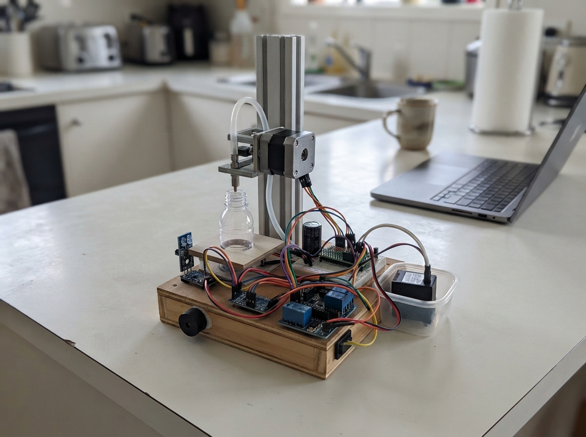
This project automates the filling and capping of bottles using an Arduino Uno to coordinate a conveyor system, water pump, air valve, and capping motor. The guide provides a complete wiring diagram, parts list, and non-blocking firmware that safely manages bottle detection, timed filling, and capping operations with emergency stop capability.
Builders will learn how to integrate IR sensors for bottle positioning, stepper motor control for conveyor indexing, relay-driven pumps and valves, and a DC motor for the capping head. The assembly outline prioritizes safety by wiring power distribution first, followed by sensor integration and actuator control, with a dry-run testing phase before operating with actual bottles.
Wiring diagram
Gather all the parts
Assemble it in 8 steps
1. Mount the safety parts first
Mount the red emergency-stop button where it can be hit without reaching past moving parts. Put guards around the conveyor, capping head, and pinch points. Use a preassembled enclosed 12 V supply; do not expose its mains terminals.
- Label the emergency-stop button clearly and keep the reset twist action accessible.
- The emergency-stop switch must interrupt the fused 12 V load supply, not only a software signal; a software fault must not leave a moving machine powered.
2. Wire the 12 V load path
With all power unplugged, connect the supply +12 V through a fuse to emergency_stop LINE. Connect emergency_stop LOAD to index_driver VMOT, cap_driver VIN, and the COM screw terminal on water_relay, air_relay, and valve_relay. Connect every 12 V negative lead and each motor-driver ground back to machine_supply GND.
- Use wire sized for the combined load and put the fuse close to the 12 V supply positive output.
- Never connect a motor, pump, valve, or the A4988 VMOT pin directly to an Arduino pin; the current will damage the board.
3. Connect the conveyor motor and its driver
Connect the two wires of one NEMA 17 coil to index_driver 1A and 1B, then its other coil to 2A and 2B. Connect index_driver STEP to Uno D5 and DIR to Uno D6. Connect VDD to 5V (logic power), both GND pins to GND (ground), and join RST to SLP before taking SLP to 5V. Fit vmot_capacitor directly across VMOT positive and GND negative, with its marked negative stripe at GND.
- Find each coil pair with a multimeter before connecting: the two wires that show a small resistance are one coil.
- Set the A4988 current-limit adjustment for the motor before running the conveyor.
- Do not plug or unplug the stepper motor while its driver has power; this can destroy the A4988. Swapped capacitor polarity can make the capacitor fail.
4. Wire the three bottle sensors
For each TCRT5000 sensor, connect VCC to Uno 5V (power) and GND to Uno GND (ground). Connect ir_infeed DO to D2 (arrival signal), ir_fill DO to A3 (filling-position signal), and ir_cap DO to D4 (capping-position signal).
- Aim each sensor at the bottle feature or reflector it must see, then turn its tiny adjustment screw until its indicator changes cleanly as a bottle passes.
- Keep the sensor leads away from motor and pump wires; electrical noise can cause a false bottle detection.
5. Wire the pump, air, and water valve
Connect each relay board VCC to Uno 5V (power) and GND to Uno GND (ground). Connect water_relay IN to D7 (water-pump control), air_relay IN to D8 (air-pump control), and valve_relay IN to D9 (water-valve control). Connect each relay NO terminal to the matching load positive lead: water_pump PUMP+, air_pump +, and fill_valve +. Connect each load negative lead to the 12 V supply GND (return).
- Use normally-open (NO), not normally-closed (NC), so a powered-down controller leaves the water path closed.
- Check the flow arrow on the water valve body before fitting tubing.
- Water near electronics can cause shock, corrosion, and false signals. Keep all low-voltage electronics above the plumbing, use proper hose clamps, and check for leaks with the power off first.
6. Wire the capping drive
Connect cap_driver PWM to Uno D10 (speed signal), IN1 to D11 (direction signal), IN2 to D12 (direction signal), and COM to Uno GND (shared control ground). Connect OUT1 to cap_motor M- and OUT2 to cap_motor M+. Mount the capping head so it cannot rotate loose from the motor shaft.
- If the head turns the wrong way during a low-power test, swap the two motor wires or reverse the direction logic in the code.
- Keep hands, hair, sleeves, and loose wire ends away from the capping head; it can pinch or wrap them.
7. Add the knob and indicators
Connect fill_size_knob VCC to 5V (power), GND to GND (ground), and its middle WIPER pin to A0 (fill-size signal). Connect buzzer SIG to D3 (sound signal) and its other lead to GND. Connect Uno A2 through led_resistor to the long positive leg of status_led; connect the short LED leg to GND.
- Turning the knob clockwise selects a longer fill time when its VCC outer terminal is on the right with the shaft facing you.
- The green LED slowly pulses when the machine is ready for a bottle.
- Make sure the LED long and short legs are not swapped, and keep the 220 Ω resistor in series; no resistor can damage the LED and Uno pin.
8. Test without water or caps
First raise the capping head or remove its belt, and leave water and air lines disconnected. Plug the Uno in by USB, release the emergency-stop button, then use the Deploy button. Confirm each sensor changes state, every relay is off when idle, the conveyor moves toward each station, and pressing the red button removes 12 V motion power.
- Set the three sensor positions and the 200-step ejection value before adding bottles. Then calibrate the fill knob with water into a measuring jug.
- If any motor or pump starts immediately after power-up, press the emergency-stop button and disconnect power. Change RELAY_ACTIVE_LOW in the firmware only after identifying the relay board's active level.
Review all connections
1. Connections between "ir_infeed" and "Arduino"
2. Connections between "ir_fill" and "Arduino"
3. Connections between "ir_cap" and "Arduino"
4. Connections between "index_driver" and "Arduino"
5. Connections between "vmot_capacitor" and "Arduino"
6. Connections between "water_relay" and "Arduino"
7. Connections between "air_relay" and "Arduino"
8. Connections between "valve_relay" and "Arduino"
9. Connections between "water_pump" and "Arduino"
10. Connections between "air_pump" and "Arduino"
11. Connections between "fill_valve" and "Arduino"
12. Connections between "cap_driver" and "Arduino"
13. Connections between "buzzer" and "Arduino"
14. Connections between "led_resistor" and "Arduino"
15. Connections between "status_led" and "Arduino"
16. Connections between "fill_size_knob" and "Arduino"
17. Connections between "machine_supply" and "Arduino"
18. Connections between "emergency_stop" and "Arduino"
Deploy the firmware
// Automated bottle filling and capping controller for Arduino Uno.
// All timing is non-blocking: the emergency/position inputs are checked every loop pass.

const byte IR_INFEED_PIN = 2;
const byte IR_FILL_PIN = A3;
const byte IR_CAP_PIN = 4;
const byte STEP_PIN = 5;
const byte DIR_PIN = 6;
const byte WATER_RELAY_PIN = 7;
const byte AIR_RELAY_PIN = 8;
const byte VALVE_RELAY_PIN = 9;
const byte CAP_PWM_PIN = 10;
const byte CAP_IN1_PIN = 11;
const byte CAP_IN2_PIN = 12;
const byte BUZZER_PIN = 3;
const byte LED_PIN = A2;
const byte FILL_SIZE_PIN = A0;

// Most opto-isolated relay boards turn on when their IN pin is LOW.
// Change this to HIGH only after safely testing your particular relay board.
const bool RELAY_ACTIVE_LOW = true;
const bool ENABLE_AIR_PURGE = true;

const unsigned long MIN_FILL_MS = 2000UL;
const unsigned long MAX_FILL_MS = 8000UL;
const unsigned long CAPPING_MS = 2500UL;
const unsigned long STEP_INTERVAL_US = 1600UL;
const unsigned long IDLE_PULSE_MS = 900UL;
const unsigned long MAX_INDEX_STEPS = 6000UL;
const byte CAPPING_PWM = 200;

enum MachineState { IDLE, MOVE_TO_FILL, FILLING, MOVE_TO_CAP, CAPPING, EJECT, FAULT };
MachineState state = IDLE;

unsigned long stateStartedMs = 0;
unsigned long lastStepUs = 0;
unsigned long stepsThisMove = 0;
unsigned long chosenFillMs = MIN_FILL_MS;
bool ledOn = false;

bool sensorActive(byte pin) {
  return digitalRead(pin) == LOW; // TCRT5000 comparator adjusted for active LOW.
}

void setRelay(byte pin, bool on) {
  digitalWrite(pin, (on == RELAY_ACTIVE_LOW) ? LOW : HIGH);
}

void allFluidLoadsOff() {
  setRelay(WATER_RELAY_PIN, false);
  setRelay(AIR_RELAY_PIN, false);
  setRelay(VALVE_RELAY_PIN, false);
}

void stopCapper() {
  analogWrite(CAP_PWM_PIN, 0);
  digitalWrite(CAP_IN1_PIN, LOW);
  digitalWrite(CAP_IN2_PIN, LOW);
}

void startCapper() {
  digitalWrite(CAP_IN1_PIN, HIGH);
  digitalWrite(CAP_IN2_PIN, LOW);
  analogWrite(CAP_PWM_PIN, CAPPING_PWM);
}

void beep(unsigned int frequency, unsigned long durationMs) {
  tone(BUZZER_PIN, frequency, durationMs);
}

void enterState(MachineState next) {
  state = next;
  stateStartedMs = millis();
  stepsThisMove = 0;

  if (next == MOVE_TO_FILL || next == MOVE_TO_CAP || next == EJECT) {
    digitalWrite(DIR_PIN, HIGH); // Reverse this level if the conveyor moves backwards.
  }

  if (next == FILLING) {
    chosenFillMs = map(analogRead(FILL_SIZE_PIN), 0, 1023, MIN_FILL_MS, MAX_FILL_MS);
    setRelay(VALVE_RELAY_PIN, true);
    setRelay(WATER_RELAY_PIN, true);
    setRelay(AIR_RELAY_PIN, ENABLE_AIR_PURGE);
  }

  if (next == CAPPING) {
    startCapper();
  }

  if (next == FAULT) {
    allFluidLoadsOff();
    stopCapper();
    beep(450, 600);
  }
}

void stepConveyor() {
  unsigned long nowUs = micros();
  if (nowUs - lastStepUs < STEP_INTERVAL_US) return;
  lastStepUs = nowUs;
  digitalWrite(STEP_PIN, HIGH);
  delayMicroseconds(4);
  digitalWrite(STEP_PIN, LOW);
  ++stepsThisMove;
}

bool indexTimedOut() {
  return stepsThisMove >= MAX_INDEX_STEPS;
}

void updateStatusLed() {
  if (state == IDLE) {
    bool newLedState = ((millis() / IDLE_PULSE_MS) % 2) == 0;
    if (newLedState != ledOn) {
      ledOn = newLedState;
      digitalWrite(LED_PIN, ledOn ? HIGH : LOW);
    }
  } else if (state == FAULT) {
    bool newLedState = ((millis() / 150UL) % 2) == 0;
    if (newLedState != ledOn) {
      ledOn = newLedState;
      digitalWrite(LED_PIN, ledOn ? HIGH : LOW);
    }
  } else if (ledOn) {
    ledOn = false;
    digitalWrite(LED_PIN, LOW);
  }
}

void setup() {
  pinMode(IR_INFEED_PIN, INPUT_PULLUP);
  pinMode(IR_FILL_PIN, INPUT_PULLUP);
  pinMode(IR_CAP_PIN, INPUT_PULLUP);
  pinMode(STEP_PIN, OUTPUT);
  pinMode(DIR_PIN, OUTPUT);
  pinMode(WATER_RELAY_PIN, OUTPUT);
  pinMode(AIR_RELAY_PIN, OUTPUT);
  pinMode(VALVE_RELAY_PIN, OUTPUT);
  pinMode(CAP_PWM_PIN, OUTPUT);
  pinMode(CAP_IN1_PIN, OUTPUT);
  pinMode(CAP_IN2_PIN, OUTPUT);
  pinMode(LED_PIN, OUTPUT);

  allFluidLoadsOff();
  stopCapper();
  digitalWrite(STEP_PIN, LOW);
  beep(1200, 150);
  stateStartedMs = millis();
}

void loop() {
  updateStatusLed();

  switch (state) {
    case IDLE:
      allFluidLoadsOff();
      stopCapper();
      if (sensorActive(IR_INFEED_PIN)) {
        beep(1500, 100);
        enterState(MOVE_TO_FILL);
      }
      break;

    case MOVE_TO_FILL:
      if (sensorActive(IR_FILL_PIN)) {
        beep(1200, 120);
        enterState(FILLING);
      } else if (indexTimedOut()) {
        enterState(FAULT);
      } else {
        stepConveyor();
      }
      break;

    case FILLING:
      if (millis() - stateStartedMs >= chosenFillMs) {
        allFluidLoadsOff();
        beep(1200, 150);
        enterState(MOVE_TO_CAP);
      }
      break;

    case MOVE_TO_CAP:
      if (sensorActive(IR_CAP_PIN)) {
        beep(1500, 100);
        enterState(CAPPING);
      } else if (indexTimedOut()) {
        enterState(FAULT);
      } else {
        stepConveyor();
      }
      break;

    case CAPPING:
      if (millis() - stateStartedMs >= CAPPING_MS) {
        stopCapper();
        beep(1800, 180);
        enterState(EJECT);
      }
      break;

    case EJECT:
      if (stepsThisMove >= 200UL) { // one full-step motor revolution; calibrate conveyor travel.
        beep(2100, 250);
        enterState(IDLE);
      } else {
        stepConveyor();
      }
      break;

    case FAULT:
      // Remove the obstructed bottle, then reset power to clear this protective stop.
      break;
  }

  delay(1);
}
Remix this project
Make it yours in one click
Open a full copy of this project in your own Schematik workspace, diagram, code, parts, and assembly steps included. Swap the sensor, add features, or redesign the whole thing with AI. The author's original stays untouched.