Community project
Automatic Touchless Trash Bin
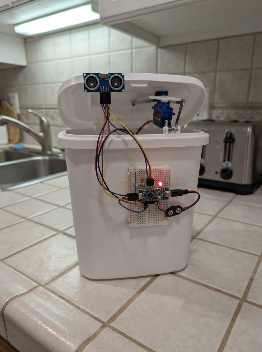
This project builds a hands-free trash bin that automatically opens its lid when a hand or object approaches within 30 centimeters. The bin uses an Arduino Uno to monitor distance with an HC-SR04 ultrasonic sensor, control a servo motor that lifts the lid, and display the bin's status with an LED indicator.
Following this guide, you'll receive a complete wiring diagram showing how to connect the distance sensor, servo, and LED to the Arduino, a full parts list, the complete firmware code, and step-by-step assembly instructions. The lid automatically closes after three seconds of no motion detected, making it convenient for contactless waste disposal.
Wiring diagram
Gather all the parts
Assemble it in 5 steps
1. Place the Uno and breadboard
Put the Arduino Uno beside the breadboard. Run one red jumper from the Uno 5V pin to the breadboard's red power rail and one black jumper from a Uno GND pin to the blue ground rail; these rails share power and ground with every part.
- Keep the board unplugged while moving wires.
- Do not connect the 5V rail to a Uno GND pin; swapped power can damage parts.
2. Wire the distance sensor
Point the HC-SR04's two round eyes outward through a hole near the front of the trashbin lid. Connect VCC to the 5V rail (power), GND to the ground rail (ground), TRIG to Uno D10 (send signal), and ECHO to Uno D11 (return signal).
- Keep the two round sensor openings uncovered so they can send and hear the ultrasonic pulse.
3. Wire the lid servo
Attach the SG90 servo firmly to the bin near its lid hinge, then connect its red wire to the 5V rail (power), brown or black wire to the ground rail (ground), and orange or yellow wire to Uno D9 (lid-control signal). Fit the servo horn to the lid linkage while the lid is in its closed position.
- Use a short, light linkage so the small servo can move the lid without binding.
- Do not force the lid by hand while the servo is powered; this can strip the small plastic gears.
4. Add the red status light
Put the red LED across the breadboard center gap. Connect its short leg, the flat-side leg, to the ground rail (ground). Connect its long leg to one lead of the 220 Ω resistor; connect the resistor's other lead to Uno D6 (light-control signal).
- The resistor can face either way. The LED only works in one direction: its long leg is the positive side.
- Do not connect the LED directly from D6 to ground without the resistor; too much current can damage the LED or Uno pin.
5. Mount and check the bin
Secure the sensor, servo, and breadboard so the moving lid cannot pull a wire loose. With the lid shut, make sure the servo arm has room to swing open and the sensor faces the approaching hand rather than the lid itself.
- The red LED turns on while the lid is open.
- If the lid moves the wrong way, move the horn on its spline or adjust the linkage before changing wiring.
- A tight or heavy lid can make the servo draw more power than a computer USB port can comfortably provide; if the Uno resets or the servo chatters, stop and use a regulated 5V supply suitable for the servo, with its ground connected to Uno GND.
Review all connections
1. Connections between "ultrasonic_1" and "Arduino"
2. Connections between "lid_servo_1" and "Arduino"
3. Connections between "led_resistor_1" and "Arduino"
4. Connections between "status_led_1" and "Arduino"
Deploy the firmware
#include <Arduino.h>
#include <Servo.h>

const uint8_t TRIG_PIN = 10;
const uint8_t ECHO_PIN = 11;
const uint8_t SERVO_PIN = 9;
const uint8_t LED_PIN = 6;

const int OPEN_DISTANCE_CM = 30;
const int LID_CLOSED_ANGLE = 10;
const int LID_OPEN_ANGLE = 100;
const unsigned long SAMPLE_INTERVAL_MS = 100;
const unsigned long HOLD_OPEN_MS = 3000;

Servo lidServo;
unsigned long lastSampleMs = 0;
unsigned long lastNearbyMs = 0;
bool lidIsOpen = false;

int readDistanceCm() {
  digitalWrite(TRIG_PIN, LOW);
  delayMicroseconds(2);
  digitalWrite(TRIG_PIN, HIGH);
  delayMicroseconds(10);
  digitalWrite(TRIG_PIN, LOW);

  unsigned long echoUs = pulseIn(ECHO_PIN, HIGH, 30000UL);
  if (echoUs == 0) {
    return -1;
  }
  return (int)(echoUs / 58UL);
}

void setLid(bool open) {
  if (open == lidIsOpen) {
    return;
  }
  lidServo.write(open ? LID_OPEN_ANGLE : LID_CLOSED_ANGLE);
  digitalWrite(LED_PIN, open ? HIGH : LOW);
  lidIsOpen = open;
}

void setup() {
  pinMode(TRIG_PIN, OUTPUT);
  pinMode(ECHO_PIN, INPUT);
  pinMode(LED_PIN, OUTPUT);
  digitalWrite(LED_PIN, LOW);

  lidServo.attach(SERVO_PIN);
  lidServo.write(LID_CLOSED_ANGLE);
}

void loop() {
  unsigned long now = millis();

  if (now - lastSampleMs >= SAMPLE_INTERVAL_MS) {
    lastSampleMs = now;
    int distanceCm = readDistanceCm();
    if (distanceCm > 0 && distanceCm <= OPEN_DISTANCE_CM) {
      lastNearbyMs = now;
      setLid(true);
    }
  }

  if (lidIsOpen && now - lastNearbyMs >= HOLD_OPEN_MS) {
    setLid(false);
  }

  delay(5);
}
Remix this project
Make it yours in one click
Open a full copy of this project in your own Schematik workspace, diagram, code, parts, and assembly steps included. Swap the sensor, add features, or redesign the whole thing with AI. The author's original stays untouched.