Community project
Voice-Enabled Robot Desk Buddy
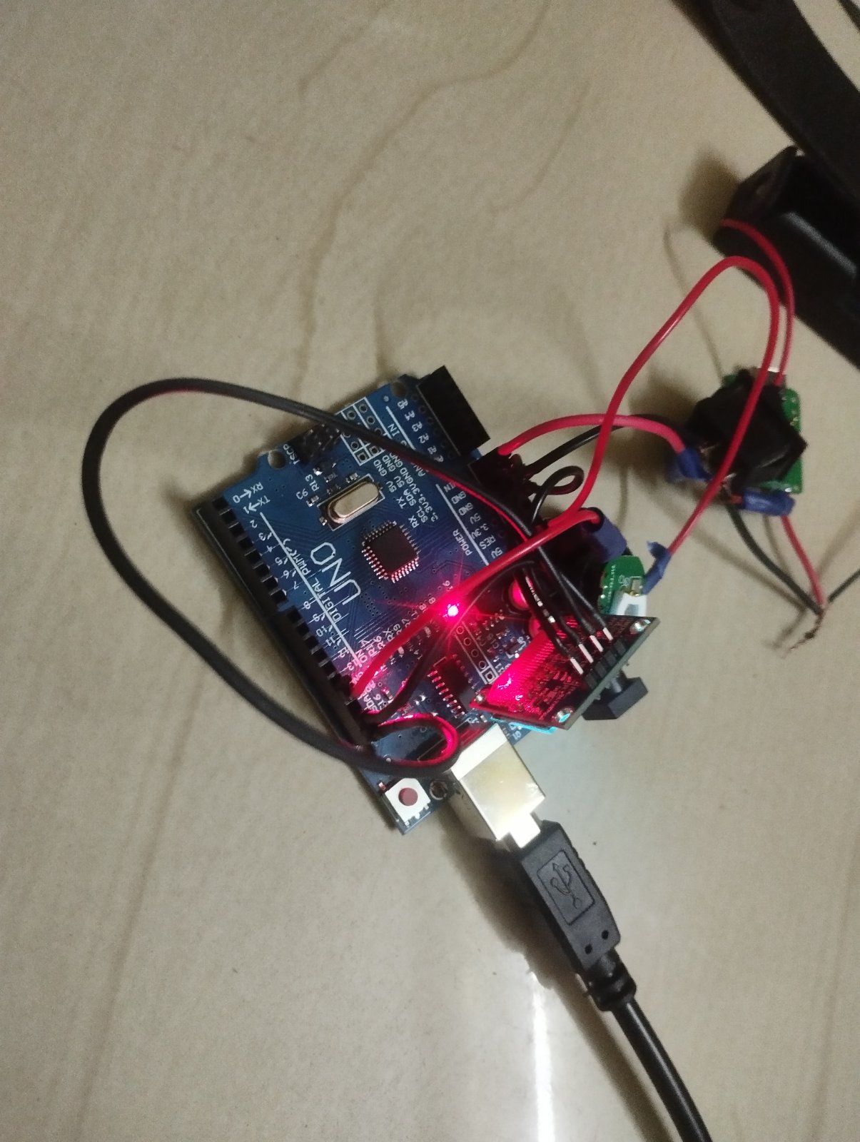
This project builds a desk companion that displays messages and reacts to Bluetooth commands from a paired phone. The device features a friendly animated face on an OLED screen, responds to button presses with sound feedback, and receives text messages wirelessly via the HC-05 Bluetooth module.
The guide includes a complete wiring diagram showing how to connect the screen, Bluetooth module, button, and buzzer to an Arduino Uno, a full parts list with recommended suppliers, ready-to-upload firmware, and step-by-step assembly instructions. Makers will learn how to set up Bluetooth communication, drive an OLED display with custom graphics, and handle wireless input on a microcontroller.
Wiring diagram
Gather all the parts
Assemble it in 6 steps
1. Place the Uno and screen
Put the Arduino Uno and the 0.96-inch OLED on the breadboard or beside it. Connect the OLED GND pin to an Uno GND pin and its VCC pin to the Uno 5V pin; the labels on some OLED boards are in a different order, so follow the printed labels rather than pin position.
- The small screen must have four pins labeled GND, VCC, SCL, and SDA.
- Do not swap the OLED VCC and GND wires; swapped power can damage the screen.
2. Wire the screen data pins
Connect OLED SDA to Uno A4 and OLED SCL to Uno A5. These two wires carry the picture data and clock from the Uno to the screen.
- A4 and A5 are the analogue pins along the lower edge of the Uno; they also have the printed SDA and SCL labels on many boards.
3. Add the Bluetooth module safely
Connect HC-05 Vcc to Uno 5V and HC-05 GND to Uno GND. Connect HC-05 TX to Uno D2. To protect the HC-05 RX pin, connect Uno D3 through the 1 kΩ resistor to HC-05 RX, then connect the 2 kΩ resistor from that same HC-05 RX point to GND. This pair of resistors lowers the Uno's 5 V signal to a safer level for the Bluetooth module.
- The two resistor legs that meet HC-05 RX must share one breadboard row with the HC-05 RX wire.
- Leave the HC-05 KEY and STATE pins unconnected.
- Do not connect Uno D3 straight to HC-05 RX; the Uno sends a 5 V signal and the module's data input is a lower-voltage signal.
4. Fit the button
Put the push button so it bridges the centre gap of the breadboard. Connect one button side to Uno D4 and the opposite side to GND. Pressing it asks the paired phone for a reply.
- The two legs on the same side of a four-leg button are already joined inside the button; use a leg from each opposite side.
5. Add the sounder
Connect the piezo buzzer SIG lead to Uno D9 and its other lead to GND. The buzzer beeps when a request is sent or text arrives from the phone.
- This piezo buzzer is not polarised, so either lead can be the SIG lead.
- Use only the small piezo buzzer, not a larger speaker or motor directly on D9; a larger load can damage the Uno pin.
6. Power and pair the desk buddy
Check that every module shares the Uno GND connection, then plug the Uno into USB. After deployment, pair a phone with the HC-05 and use a Bluetooth serial app or phone automation that sends a short text reply followed by a new line. When you press the button, the Uno sends the word LISTEN to that phone.
- The normal HC-05 data-mode speed is 9600 baud.
- The Uno cannot understand spoken words or look up answers itself; the paired phone supplies speech recognition and the online assistant response.
- Use a USB power source for the Uno while building; do not connect a battery and USB power at the same time.
Review all connections
1. Connections between "oled_face" and "Arduino"
2. Connections between "talk_button" and "Arduino"
3. Connections between "bluetooth" and "Arduino"
4. Connections between "bt_rx_series" and "Arduino"
5. Connections between "bt_rx_ground" and "Arduino"
6. Connections between "buzzer" and "Arduino"
Deploy the firmware
#include <Wire.h>
#include <SoftwareSerial.h>
#include <Adafruit_GFX.h>
#include <Adafruit_SSD1306.h>

const uint8_t BUTTON_PIN = 4;
const uint8_t BT_RX_PIN = 2;  // Arduino receives from HC-05 TX
const uint8_t BT_TX_PIN = 3;  // Arduino sends through the 1k/2k divider to HC-05 RX
const uint8_t BUZZER_PIN = 9;

Adafruit_SSD1306 display(128, 64, &Wire, -1);
SoftwareSerial bluetooth(BT_RX_PIN, BT_TX_PIN);

char replyText[97] = "Pair phone, then send text";
char previousText[97] = "";
bool lastButton = HIGH;
unsigned long lastButtonChange = 0;

void drawFace(const char *message) {
  if (strcmp(message, previousText) == 0) return;
  strncpy(previousText, message, sizeof(previousText) - 1);
  previousText[sizeof(previousText) - 1] = '\0';

  display.clearDisplay();
  display.drawCircle(35, 18, 6, SSD1306_WHITE);
  display.drawCircle(93, 18, 6, SSD1306_WHITE);
  display.fillCircle(35, 18, 2, SSD1306_WHITE);
  display.fillCircle(93, 18, 2, SSD1306_WHITE);
  display.drawLine(45, 39, 55, 45, SSD1306_WHITE);
  display.drawLine(55, 45, 65, 47, SSD1306_WHITE);
  display.drawLine(65, 47, 75, 45, SSD1306_WHITE);
  display.drawLine(75, 45, 85, 39, SSD1306_WHITE);
  display.drawFastHLine(0, 52, 128, SSD1306_WHITE);
  display.setTextSize(1);
  display.setTextColor(SSD1306_WHITE);
  display.setCursor(0, 55);
  display.print(message);
  display.display();
}

void receiveReply() {
  static char incoming[97];
  static uint8_t length = 0;

  while (bluetooth.available()) {
    char c = (char)bluetooth.read();
    if (c == '\r') continue;
    if (c == '\n') {
      if (length > 0) {
        incoming[length] = '\0';
        strncpy(replyText, incoming, sizeof(replyText) - 1);
        replyText[sizeof(replyText) - 1] = '\0';
        drawFace(replyText);
        tone(BUZZER_PIN, 3000, 80);
        length = 0;
      }
    } else if (c >= 32 && c <= 126 && length < sizeof(incoming) - 1) {
      incoming[length++] = c;
    }
  }
}

void setup() {
  pinMode(BUTTON_PIN, INPUT_PULLUP);
  pinMode(BUZZER_PIN, OUTPUT);
  bluetooth.begin(9600);

  display.begin(SSD1306_SWITCHCAPVCC, 0x3C);
  drawFace("Pair phone, then send text");
  tone(BUZZER_PIN, 2400, 80);
}

void loop() {
  receiveReply();

  bool buttonNow = digitalRead(BUTTON_PIN);
  if (lastButton == HIGH && buttonNow == LOW && millis() - lastButtonChange > 40) {
    lastButtonChange = millis();
    bluetooth.println("LISTEN");
    drawFace("Ask phone... waiting");
    tone(BUZZER_PIN, 2400, 120);
  }
  lastButton = buttonNow;
  delay(5);
}
Remix this project
Make it yours in one click
Open a full copy of this project in your own Schematik workspace, diagram, code, parts, and assembly steps included. Swap the sensor, add features, or redesign the whole thing with AI. The author's original stays untouched.