Community project
Automatic Fan And Light
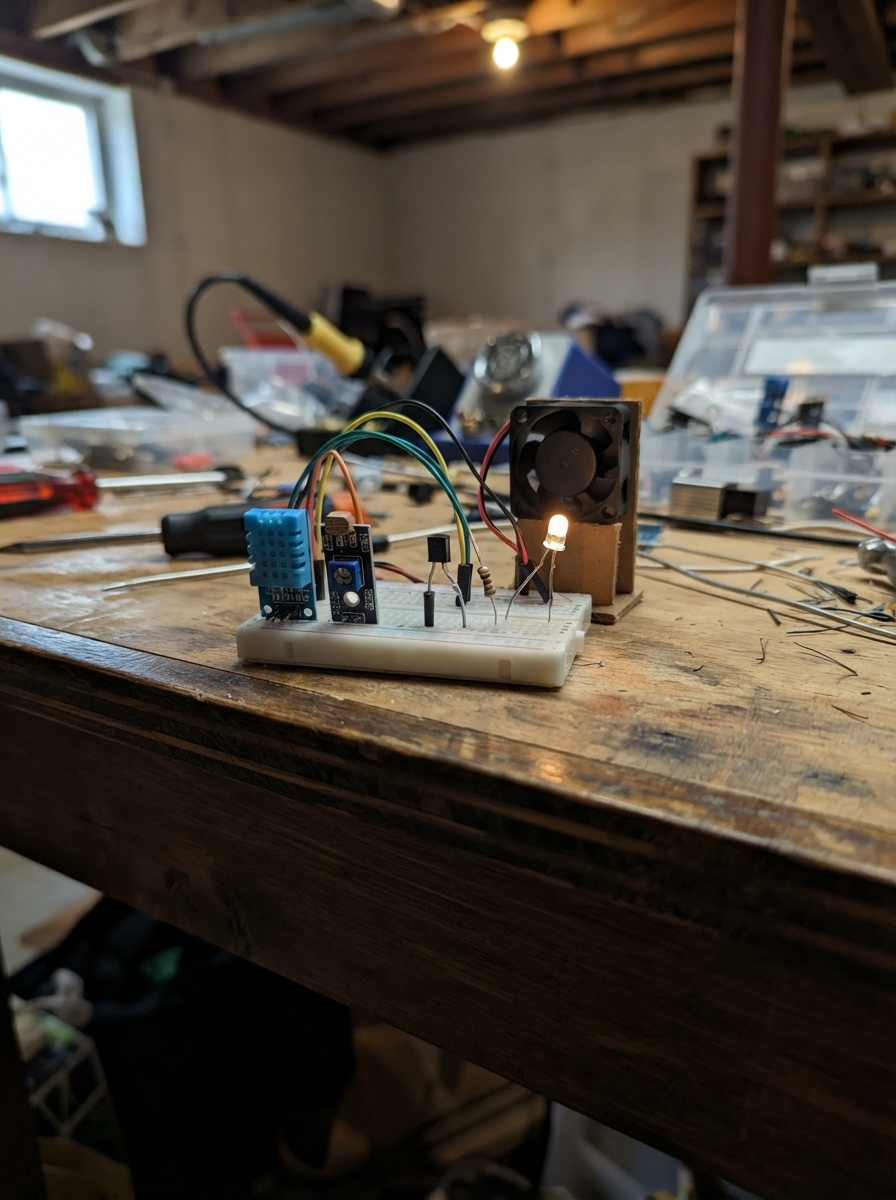
This project builds an automatic lighting system that turns on a lamp when the surrounding light level drops below a set threshold. The system uses a DHT11 temperature and humidity sensor to monitor environmental conditions and an LDR light sensor module to detect darkness, with an Arduino Uno coordinating the logic and controlling the lamp via an NPN transistor.
Builders will receive a complete wiring diagram showing how to connect the DHT11 and LDR modules to the Arduino, a parts list with all required components, ready-to-upload firmware that reads both sensors and manages the lamp output, and step-by-step assembly instructions including how to calibrate the light threshold and verify operation through the serial monitor.
Wiring diagram

Gather all the parts
Assemble it in 6 steps
1. Rút USB trước khi nối dây
Rút cáp USB khỏi Arduino trước khi cắm hoặc đổi dây. Dùng breadboard hoặc một điểm nối chung để chia nguồn 5V và GND cho các mô-đun.
- Chỉ cắm USB lại sau khi đã kiểm tra toàn bộ dây.
- Nếu dây 5V và GND chạm nhau, Arduino hoặc cáp USB có thể nóng lên.
2. Nối DHT11
Trên mô-đun DHT11 ghi +, OUT, −: nối + → chân 5V Arduino (nguồn), − → chân GND Arduino (ground), OUT → chân D2 (dữ liệu).
- Nối theo chữ in trên mạch, không dựa vào màu dây.
- Đừng đổi + và −; cấp nguồn ngược có thể làm hỏng mô-đun.
3. Nối mô-đun cảm biến ánh sáng
Nối VCC của mô-đun LDR → chân 5V Arduino (nguồn), GND → chân GND Arduino (ground), OUT → chân D4 (tín hiệu).
- Vặn biến trở nhỏ trên mô-đun để chọn mức tối mà bạn muốn đèn bật.
- Đừng đổi VCC và GND; nối ngược nguồn có thể làm hỏng mô-đun.
4. Nối transistor và điện trở điều khiển đèn
Xem đúng sơ đồ chân E, B, C của chiếc transistor 2N2222 bạn mua, vì các phiên bản vỏ khác nhau có thể có thứ tự chân khác nhau. Nối Arduino D9 → một đầu điện trở 1 kΩ (lệnh bật/tắt); đầu còn lại điện trở → Base/B transistor. Nối Emitter/E → GND Arduino (đường về nguồn).
- Điện trở 1 kΩ không có chiều, lắp đầu nào vào D9 cũng được.
- Không nối D9 thẳng vào Base/B vì có thể làm quá dòng và hỏng chân Arduino hoặc transistor. Nhầm E, B, C có thể làm đèn không hoạt động hoặc làm linh kiện nóng lên.
5. Nối đèn qua transistor
Nối dây đỏ hoặc dây có dấu + của đèn → chân 5V Arduino (nguồn). Nối dây đen hoặc dây có dấu − của đèn → Collector/C của transistor (đường đèn được đóng/ngắt).
- Đèn ghi 3–6 V nên không cần dùng điện trở 220 Ω trong mạch này.
- Nếu đèn, transistor, dây nguồn hoặc Arduino nóng lên, rút USB ngay. Không nối dây âm của đèn trực tiếp vào GND, vì như vậy đèn sẽ luôn sáng.
6. Cấp nguồn và thử ngưỡng tối
Cắm Arduino vào USB. Che mặt cảm biến LDR để mô-đun báo tối: đèn sẽ bật. Chiếu sáng lại cảm biến: đèn sẽ tắt. Nếu hoạt động ngược, vặn biến trở nhỏ trên mô-đun LDR đến khi chuyển đúng ở mức ánh sáng bạn muốn.
- Mã cũng đọc nhiệt độ và độ ẩm DHT11 mỗi 2 giây để bạn kiểm tra trong phần Serial của Schematik.
- Chỉ dùng đèn 3–6 V dòng nhỏ với nguồn 5V từ Arduino USB. Nếu đèn làm Arduino nóng, cần nguồn 5V ngoài đủ dòng và phải nối GND hai nguồn chung.
Review all connections
1. Connections between "dht11_1" and "Arduino"
2. Connections between "ldr_module_1" and "Arduino"
3. Connections between "lamp_3to6v_1" and "Arduino"
4. Connections between "transistor_lamp_1" and "Arduino"
5. Connections between "resistor_lamp_base_1" and "Arduino"
Deploy the firmware
#include <DHT.h>

#define DHT_PIN 2
#define DHT_TYPE DHT11
#define LDR_OUT_PIN 4
#define LAMP_PIN 9

DHT dht(DHT_PIN, DHT_TYPE);
unsigned long lastSensorReadMs = 0;
const unsigned long SENSOR_INTERVAL_MS = 2000;

void setup() {
  Serial.begin(9600);

  pinMode(LDR_OUT_PIN, INPUT);
  pinMode(LAMP_PIN, OUTPUT);
  digitalWrite(LAMP_PIN, LOW);  // Start with the lamp off.

  dht.begin();
  Serial.println(F("Cam bien DHT11 va LDR da san sang."));
}

void loop() {
  // Most common LDR comparator modules pull OUT LOW when the light level is below
  // the threshold set by their small adjustment screw.
  bool dark = (digitalRead(LDR_OUT_PIN) == LOW);
  // The LDR module normally sends LOW when its adjustment threshold sees darkness.
  digitalWrite(LAMP_PIN, dark ? HIGH : LOW);

  unsigned long now = millis();
  if (now - lastSensorReadMs < SENSOR_INTERVAL_MS) {
    return;
  }
  lastSensorReadMs = now;

  float temperatureC = dht.readTemperature();
  float humidity = dht.readHumidity();
  if (isnan(temperatureC) || isnan(humidity)) {
    Serial.println(F("Khong doc duoc DHT11. Kiem tra VCC, GND va DATA."));
    return;
  }

  Serial.print(F("Nhiet do: "));
  Serial.print(temperatureC, 1);
  Serial.print(F(" C | Do am: "));
  Serial.print(humidity, 0);
  Serial.print(F(" % | LDR: "));
  Serial.print(dark ? F("TOI") : F("SANG"));
  Serial.println(dark ? F(" | Den: BAT") : F(" | Den: TAT"));
}
Remix this project
Make it yours in one click
Open a full copy of this project in your own Schematik workspace — diagram, code, parts, and assembly steps included. Swap the sensor, add features, or redesign the whole thing with AI. The author's original stays untouched.