Community project
ESP32 PWM LED Dimmer
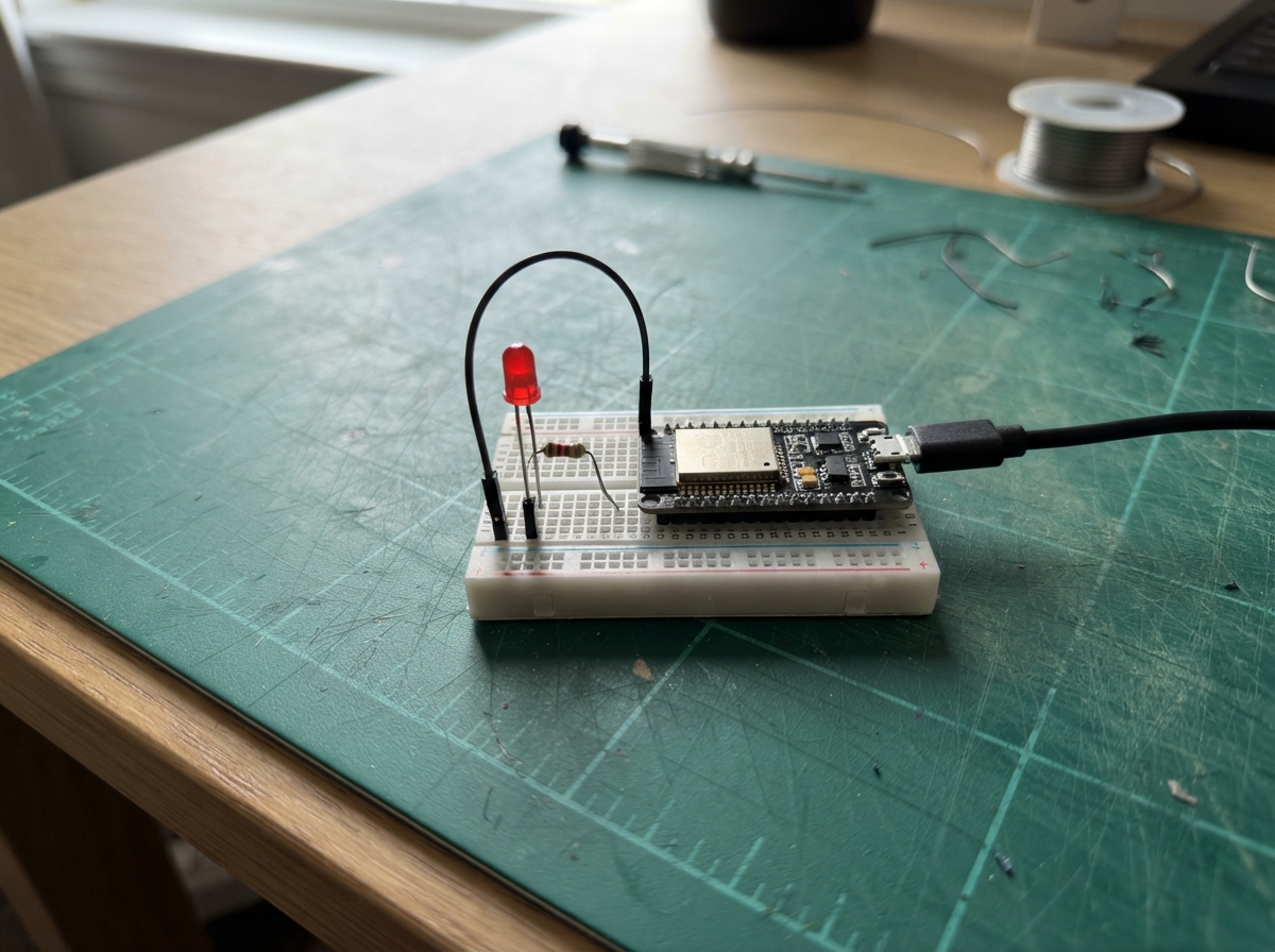
This project demonstrates PWM (Pulse Width Modulation) by fading an LED smoothly up and down. The Arduino board rapidly switches a digital pin on and off; by adjusting how long the pin stays on during each cycle, the LED's brightness appears to change continuously from off to full brightness and back again.
The guide includes a wiring diagram showing how to connect the LED and current-limiting resistor to the Arduino, a complete parts list, and the firmware code that controls the fade effect. Builders will learn how PWM works and how to use it to control LED brightness or other analog-like effects on a digital microcontroller.
Wiring diagram

Gather all the parts
Review all connections
1. Connections between "resistor_1" and "Arduino"
2. Connections between "led_1" and "Arduino"
Deploy the firmware
// Basic PWM Output Signal — LED fade demonstration.
// PWM sends very fast ON/OFF pulses; changing the ON-time changes the LED's apparent brightness.

const byte LED_PWM_PIN = 9;        // D9 is connected to the resistor, then the LED's long leg.
int brightness = 0;                // Store the PWM level: 0 is off and 255 is fully on.
int fadeAmount = 5;                // Store how much the brightness changes on each update.

void setup() {                     // This function runs once after the board starts.
  pinMode(LED_PWM_PIN, OUTPUT);     // Make D9 an output so it can drive the LED.
}                                   // setup() is complete.

void loop() {                      // This function repeats forever.
  analogWrite(LED_PWM_PIN, brightness); // Output PWM: larger brightness keeps the LED on longer each cycle.
  brightness = brightness + fadeAmount; // Calculate the next brightness level.

  if (brightness <= 0 || brightness >= 255) { // Check whether the fade reached either end.
    fadeAmount = -fadeAmount;       // Reverse direction so the LED fades back the other way.
  }                                 // The direction check is complete.

  delay(30);                        // Wait 30 milliseconds so the change looks smooth to your eyes.
}                                   // loop() starts again from the top.
Remix this project
Make it yours in one click
Open a full copy of this project in your own Schematik workspace — diagram, code, parts, and assembly steps included. Swap the sensor, add features, or redesign the whole thing with AI. The author's original stays untouched.