Community project
Automatic Plant Watering
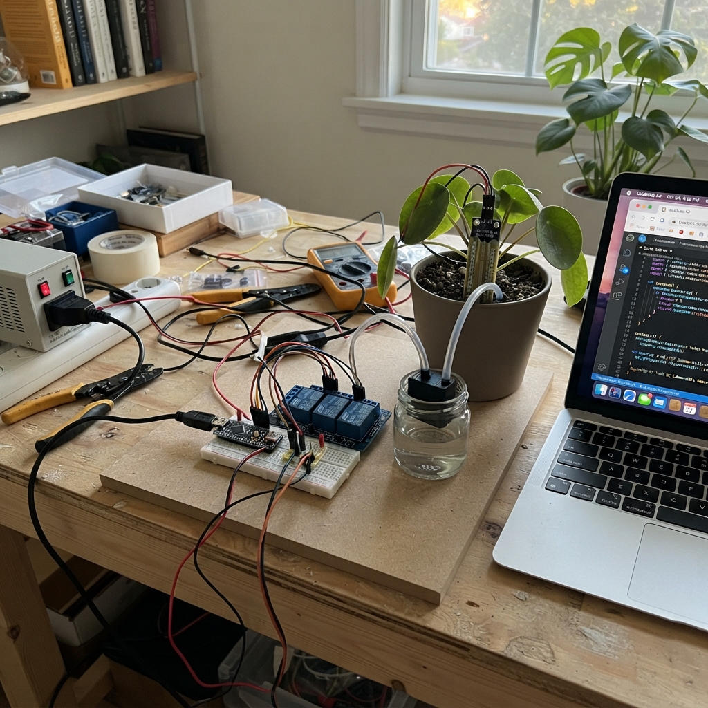
This project automates watering for up to four potted plants using capacitive soil moisture sensors and individual relay-controlled water pumps. The Arduino Uno continuously monitors each plant's soil moisture level and triggers its pump to run for a set duration whenever the soil dries below a configurable threshold, with a built-in delay between waterings to prevent overwatering.
The guide provides a complete wiring diagram, parts list, and step-by-step assembly instructions for safely integrating the power supply, relay module, sensors, and pumps. Included firmware handles sensor calibration, moisture calculation, and pump scheduling with serial output for monitoring and debugging each plant's watering cycle.
Wiring diagram

Gather all the parts
Assemble it in 7 steps
1. Set up safe power first
Keep the Uno unplugged. Do not use the rectangular 9V battery as the pump supply: it cannot reliably provide the pump startup current. Use a regulated 5V supply rated for at least 3A for the pumps and relay. Leave the small yellow JD-VCC jumper installed on the relay board. Power the Uno from its USB cable.
- Put a strip of masking tape on the 5V supply wires: red for +5V and black for GND.
- Keep water containers and wet tubing away from the Uno, relay module, breadboard, and USB connector.
- Do not connect the pump supply's +5V wire to the Uno 5V pin. The pumps must receive power through the relay contacts, not through the Uno.
- Do not use the 9V battery with the breadboard supply for the pumps; voltage sag can cause unreliable pumping and Arduino resets.
2. Make the shared ground rail
Use the blue breadboard rail as ground. Run a black jumper from an Uno GND pin to that rail. Run another black jumper from the regulated pump supply GND to the same rail. This shared return path lets the Uno correctly control the relay board.
- All black ground wires must be electrically joined on the same blue rail.
- A missing shared ground can make relays chatter, fail to switch, or turn on unexpectedly.
3. Wire the four soil probes
Use the Uno's 5V pin only for the soil probes. Run one red jumper from Uno 5V to a separate red sensor-power rail, then connect every sensor VCC to it. Connect every sensor GND to the blue ground rail with black jumpers. Connect sensor 1 AOUT to Uno A0 with a yellow jumper, sensor 2 AOUT to A1 with a green jumper, sensor 3 AOUT to A2 with a blue jumper, and sensor 4 AOUT to A3 with a white jumper. Put sensor 1 in your first pot now; the other three can be connected when you expand.
- VCC → Uno 5V (power); each GND → shared blue rail (ground); AOUT → A0/A1/A2/A3 (moisture signal).
- Push only the coated sensing end into soil. Keep the small circuit board above the soil and dry.
- Make sure VCC and GND are not swapped — swapped power can damage a sensor.
4. Wire the relay control side
With the JD-VCC jumper still fitted, connect relay VCC to the regulated pump supply +5V with a red jumper and relay GND to the shared blue ground rail with a black jumper. Connect relay IN1 to Uno D2 with a yellow jumper, IN2 to D3 with a green jumper, IN3 to D4 with a blue jumper, and IN4 to D5 with a white jumper. The common 4-channel relay type is active-LOW, so the uploaded code keeps these pins HIGH to leave every pump off.
- Control wires: IN1 → D2 (pump 1 control), IN2 → D3 (pump 2 control), IN3 → D4 (pump 3 control), IN4 → D5 (pump 4 control).
- The small LEDs on the relay board usually light when a channel is active.
- Do not remove the JD-VCC jumper for this beginner build. The separate relay-coil wiring required without it is different.
- Before attaching water tubing, plug in the Uno and confirm no relay channel clicks on at startup.
5. Wire pump 1 through relay channel 1
For the first pot, run a thicker red wire from the regulated pump supply +5V to relay COM1. Run a red wire from relay NO1 to pump 1 positive wire. Connect pump 1 negative wire to the shared blue ground rail with a black wire. Place diode 1 directly across the pump wires: its striped end goes to pump positive / the NO1 wire, and its unstriped end goes to pump negative / ground. NO means the pump stays off until the relay is commanded on.
- Pump 1: supply +5V → COM1 (power); NO1 → pump positive (switched power); pump negative → shared ground (return).
- The stripe on a 1N4007 diode marks its cathode; it must face the pump positive wire.
- A reversed flyback diode makes a short circuit when the pump relay turns on and can damage the supply or wiring.
- Keep the diode leads insulated so they cannot touch each other or wet surfaces.
6. Reserve matching wiring for pots 2 through 4
When you add the other pots, repeat the same switched-positive wiring: pump supply +5V to COM2, COM3, and COM4; NO2 to pump 2 positive, NO3 to pump 3 positive, and NO4 to pump 4 positive; each pump negative to the shared ground rail. Place a diode across each pump with its striped end on that pump's positive wire and unstriped end on that pump's negative wire. Connect tubing from each pump to its own pot.
- Pump 2 uses relay channel 2, pump 3 uses channel 3, and pump 4 uses channel 4.
- Keep each pump submerged in its water container before testing; running a small submersible pump dry can shorten its life.
- Do not join the four NO terminals together: each NO terminal must feed only its own pump so the code can water one pot at a time.
7. Place tubing and perform a dry safety check
Put each pump in a water container, attach tubing firmly, and route each tube end into its matching pot. Keep all electronics higher than the water level. Before watering a real plant, test with a cup or tray under the tube. Upload the code through Schematik's Deploy button, then open the Serial Monitor at 9600 baud to see the raw readings and moisture percentages.
- For the one-pot start, connect only sensor 1 and pump 1 physically; the code already reserves the other three channels.
- Adjust MOISTURE_THRESHOLD_PERCENT and PUMP_RUN_MS only after observing how much water reaches your pot in three seconds.
- Unplug both USB and the pump supply before moving wires.
- If a pump runs immediately after startup, unplug the pump supply first, then check that the relay input wiring and active-LOW setting match the code.
Review all connections
1. Connections between "soil_sensor_1" and "Arduino"
2. Connections between "soil_sensor_2" and "Arduino"
3. Connections between "soil_sensor_3" and "Arduino"
4. Connections between "soil_sensor_4" and "Arduino"
5. Connections between "relay_4ch" and "Arduino"
6. Connections between "pump_1" and "Arduino"
7. Connections between "pump_2" and "Arduino"
8. Connections between "pump_3" and "Arduino"
9. Connections between "pump_4" and "Arduino"
10. Connections between "flyback_diode_1" and "Arduino"
11. Connections between "flyback_diode_2" and "Arduino"
12. Connections between "flyback_diode_3" and "Arduino"
13. Connections between "flyback_diode_4" and "Arduino"
14. Connections between "pump_supply_5v" and "Arduino"
Deploy the firmware
// Automatic plant watering controller for Arduino Uno.
// Relay modules like the common 4-channel optocoupler board normally turn ON
// when their IN pin is LOW. If yours behaves opposite, swap these two values.
const byte RELAY_ON = LOW;
const byte RELAY_OFF = HIGH;

const byte SOIL_PINS[4] = {A0, A1, A2, A3};
const byte RELAY_PINS[4] = {2, 3, 4, 5};

// Calibration values: larger reading = drier for these capacitive probes.
// Change each pair after testing that particular sensor in air and in wet soil.
const int DRY_READING[4] = {654, 654, 654, 654};
const int WET_READING[4] = {330, 330, 330, 330};

// A plant is watered when its reading is below this percentage.
const int MOISTURE_THRESHOLD_PERCENT = 35;
const unsigned long PUMP_RUN_MS = 3000UL;             // 3 seconds per watering
const unsigned long RECHECK_DELAY_MS = 30UL * 60000UL; // 30 minutes
const unsigned long REPORT_INTERVAL_MS = 5000UL;       // serial report every 5 seconds

unsigned long nextAllowedWaterTime[4] = {0, 0, 0, 0};
unsigned long lastReportTime = 0;

int readAverageRaw(byte sensorIndex) {
  const byte samples = 10;
  long total = 0;
  for (byte i = 0; i < samples; i++) {
    total += analogRead(SOIL_PINS[sensorIndex]);
    delay(5);
  }
  return total / samples;
}

int rawToMoisturePercent(byte sensorIndex, int raw) {
  long percent = map(raw, DRY_READING[sensorIndex], WET_READING[sensorIndex], 0, 100);
  return constrain(percent, 0, 100);
}

void allPumpsOff() {
  for (byte i = 0; i < 4; i++) {
    digitalWrite(RELAY_PINS[i], RELAY_OFF);
  }
}

void waterOnePot(byte potIndex) {
  // allPumpsOff makes this safe even after changing the program later:
  // only one relay, and therefore only one pump, can run at a time.
  allPumpsOff();
  Serial.print(F("Watering pot "));
  Serial.print(potIndex + 1);
  Serial.print(F(" for "));
  Serial.print(PUMP_RUN_MS / 1000UL);
  Serial.println(F(" seconds."));

  digitalWrite(RELAY_PINS[potIndex], RELAY_ON);
  delay(PUMP_RUN_MS);
  digitalWrite(RELAY_PINS[potIndex], RELAY_OFF);

  nextAllowedWaterTime[potIndex] = millis() + RECHECK_DELAY_MS;
  Serial.print(F("Pump "));
  Serial.print(potIndex + 1);
  Serial.println(F(" stopped; this pot will wait before it can water again."));
}

void reportMoisture() {
  Serial.println(F("--- Soil moisture ---"));
  for (byte i = 0; i < 4; i++) {
    int raw = readAverageRaw(i);
    int percent = rawToMoisturePercent(i, raw);
    Serial.print(F("Pot "));
    Serial.print(i + 1);
    Serial.print(F(": raw "));
    Serial.print(raw);
    Serial.print(F(", moisture "));
    Serial.print(percent);
    Serial.println(F("%"));
  }
}

void setup() {
  Serial.begin(9600);

  for (byte i = 0; i < 4; i++) {
    pinMode(RELAY_PINS[i], OUTPUT);
  }
  allPumpsOff(); // critical for active-LOW relay boards: pumps stay off at startup

  Serial.println(F("Automatic plant watering controller ready."));
  Serial.println(F("Open Serial Monitor at 9600 baud."));
}

void loop() {
  unsigned long now = millis();

  if (now - lastReportTime >= REPORT_INTERVAL_MS) {
    lastReportTime = now;
    reportMoisture();
  }

  // Check each pot in order.  waterOnePot blocks briefly on purpose, so no
  // second pump can begin while the first pump is running.
  for (byte i = 0; i < 4; i++) {
    if (now >= nextAllowedWaterTime[i]) {
      int raw = readAverageRaw(i);
      int moisture = rawToMoisturePercent(i, raw);
      if (moisture < MOISTURE_THRESHOLD_PERCENT) {
        waterOnePot(i);
        break;
      }
    }
  }
}
Remix this project
Make it yours in one click
Open a full copy of this project in your own Schematik workspace — diagram, code, parts, and assembly steps included. Swap the sensor, add features, or redesign the whole thing with AI. The author's original stays untouched.