Community project
Automatic Window Lock Alarm
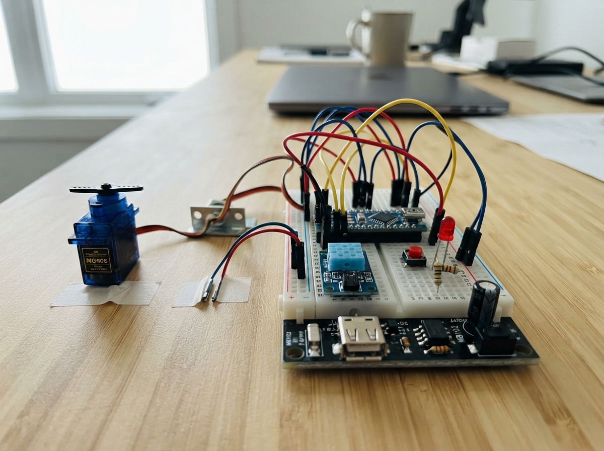
This project builds a smart window lock that combines mechanical security with electronic monitoring. The ESP32 controls a servo-driven bolt lock while monitoring a reed switch on the window frame and a vibration sensor for forced-entry attempts. The system supports multiple modes (Home, Night, Away, Alarm) with automatic locking, manual release via pushbutton, and visual status indicators.
The guide provides a complete wiring diagram, parts list, and step-by-step assembly instructions for integrating the servo, sensors, and control electronics on a breadboard. Firmware is included to handle lock/unlock logic, mode switching, sleep optimization, and event reporting. Builders will learn how to wire low-power IoT devices, debounce sensor inputs, and manage servo timing for reliable mechanical operation.
Wiring diagram

Gather all the parts
Assemble it in 7 steps
1. Keep the unsafe pins free
Place the WeAct ESP32-C6-MiNi so its USB-C connector is easy to reach. Do not connect anything to GPIO4, GPIO5, GPIO8, GPIO9, GPIO12, GPIO13, or GPIO15; these pins affect starting the board or its USB connection.
- Using those pins can stop the board from starting normally or disconnect its USB programming connection.
2. Make one shared ground
Run a black jumper from a GND pin on the ESP32-C6 to the breadboard ground rail. Connect the MB102 module GND and the MG90 brown or black wire to that same rail. This shared ground lets the 3.3 V control signal have the correct reference.
- Do not connect the servo ground only to the MB102; without the shared ground, the servo can move unpredictably.
3. Wire the servo power and signal
Connect the MG90 red wire to MB102 5V_OUT (servo power), the brown or black wire to the shared GND rail (ground), and the orange or yellow wire to GPIO18 (signal). Put the 470 µF capacitor close to the servo supply: its positive marked lead to MB102 5V_OUT (power) and its striped negative lead to the shared GND rail (ground).
- Power the MB102 from its own 5 V USB source during development; the ESP32 USB-C connection powers only the board.
- Never connect the MG90 red wire to the ESP32 3V3 pin — it cannot supply the servo and the servo requires about 5 V.
- Make sure the capacitor stripe is on ground; reversed electrolytic capacitors can overheat or fail.
4. Add the window and forced-entry sensors
Connect one MC-38 reed-switch wire to GPIO10 (signal) and the other to the shared GND rail (ground). Mount its magnet so the reed is closed when the window is fully shut. Connect the SW-420 VCC pin to ESP32 3V3 (power), GND to the shared GND rail (ground), and DO to GPIO2 (signal).
- Turn the SW-420 adjustment screw slowly while testing so a normal tap makes one clear trigger but room vibration does not.
- Keep the SW-420 on 3.3 V: powering it from 5 V could make its DO output unsafe for the ESP32-C6's 3.3 V input.
5. Add the inside release button
Place the pushbutton across the breadboard centre gap. Connect one side to GPIO11 (signal) and the opposite side to the shared GND rail (ground). The code supplies the pull-up internally, so no extra resistor is needed.
- Use two legs that are on opposite sides of the switch; legs on the same side are already connected together.
6. Add the lock-state lights
For the green light, wire GPIO6 to one lead of the 330 Ω green resistor (signal), the resistor's other lead to the green LED long leg (power path), and the green LED short leg to the shared GND rail (ground). For the red light, wire GPIO7 to one lead of the other 330 Ω resistor (signal), its other lead to the red LED long leg (power path), and the red LED short leg to the shared GND rail (ground).
- Do not omit either 330 Ω resistor — without it, an LED can be damaged by too much current.
7. Set up the sleep-current measurement
For the battery test, disconnect the MB102 servo power lead so the servo supply is not part of the reading. Put three AA cells in series, then break the positive wire between the AA pack and the ESP32 5 V pin. Put the multimeter in DC-current mode in that gap: red meter lead to battery positive and black meter lead to the ESP32 5 V pin. Keep battery negative connected directly to ESP32 GND (ground).
- Set MEASURE_MODE to 1 in the firmware before deploying for a steadier sleeping reading, then reconnect the servo supply only for movement tests.
- Start with the meter's highest current range and move down only after you confirm the reading is small; using a low range during a servo test can blow the meter fuse.
- Do not power the board simultaneously from USB-C and the AA pack during this measurement.
Review all connections
1. Connections between "servo_mg90" and "ESP32"
2. Connections between "reed_mc38" and "ESP32"
3. Connections between "vibration_sw420" and "ESP32"
4. Connections between "release_button" and "ESP32"
5. Connections between "green_resistor" and "ESP32"
6. Connections between "green_led" and "ESP32"
7. Connections between "red_resistor" and "ESP32"
8. Connections between "red_led" and "ESP32"
9. Connections between "mb102_5v" and "ESP32"
10. Connections between "servo_capacitor" and "ESP32"
Deploy the firmware
#include <Arduino.h>
#include <ESP32Servo.h>
#include "esp_sleep.h"
#include "driver/gpio.h"

// Thread/CoAP transport boundary: implemented as Serial stubs in src/thread_stubs.cpp.
void sendEvent(const char *name);
void onCommand(const char *cmd);
void onMode(const char *mode);
const char *getState();

constexpr int SERVO_PIN = 18;
constexpr int REED_PIN = 10;
constexpr int VIBRATION_PIN = 2;
constexpr int RELEASE_PIN = 11;
constexpr int GREEN_LED_PIN = 6;
constexpr int RED_LED_PIN = 7;

constexpr int SERVO_UNLOCK_ANGLE = 0;
constexpr int SERVO_LOCK_ANGLE = 90;
constexpr uint32_t SERVO_SETTLE_MS = 300;
constexpr uint32_t FORCED_WINDOW_MS = 2000;
constexpr uint32_t REMOTE_UNLOCK_RELOCK_MS = 15UL * 60UL * 1000UL; // Shorten for demonstrations.
constexpr uint32_t INPUT_DEBOUNCE_MS = 25;
constexpr uint64_t TIMER_WAKE_US = 1000000ULL;

// Change to LOW if the fitted SW-420 module asserts low when vibration is detected.
#define VIBRATION_ACTIVE_LEVEL HIGH
// Change to 1 for the sleep-current test. It removes the 1-second timer wake.
#define MEASURE_MODE 0

enum Mode { HOME, NIGHT, AWAY, ALARM, SMOKE };

Servo boltServo;
Mode mode = HOME;
bool isLocked = false;
bool remoteUnlockPending = false;
bool previousWindowShut = false;
bool sawWindowOpenDuringRemoteUnlock = false;
uint32_t remoteUnlockAt = 0;
uint32_t firstVibrationAt = 0;
uint32_t lastReleaseAt = 0;
bool lastVibrationActive = false;
String serialLine;

bool windowIsShut() { return digitalRead(REED_PIN) == LOW; }
bool vibrationIsActive() { return digitalRead(VIBRATION_PIN) == VIBRATION_ACTIVE_LEVEL; }

const char *modeName(Mode value) {
  switch (value) {
    case HOME: return "home";
    case NIGHT: return "night";
    case AWAY: return "away";
    case ALARM: return "alarm";
    case SMOKE: return "smoke";
  }
  return "home";
}

void updateIndicators() {
  digitalWrite(RED_LED_PIN, isLocked ? HIGH : LOW);
  digitalWrite(GREEN_LED_PIN, isLocked ? LOW : HIGH);
}

void moveBolt(bool lock) {
  if (isLocked == lock) return;
  boltServo.setPeriodHertz(50);
  boltServo.attach(SERVO_PIN, 500, 2500);
  boltServo.write(lock ? SERVO_LOCK_ANGLE : SERVO_UNLOCK_ANGLE);
  delay(SERVO_SETTLE_MS);
  boltServo.detach(); // Removes drive pulses after each move, saving power and preventing buzz.
  isLocked = lock;
  updateIndicators();
  Serial.println(lock ? "BOLT locked" : "BOLT unlocked");
}

void lockNow(const char *eventName) {
  if (!windowIsShut()) {
    Serial.println("LOCK skipped: window is open");
    return;
  }
  moveBolt(true);
  if (eventName != nullptr) sendEvent(eventName);
}

void unlockNow(const char *eventName) {
  moveBolt(false);
  if (eventName != nullptr) sendEvent(eventName);
}

void applyModePolicy() {
  if (mode == SMOKE) {
    remoteUnlockPending = false;
    unlockNow("smoke_unlock");
  } else if ((mode == NIGHT || mode == AWAY || mode == ALARM) && windowIsShut()) {
    remoteUnlockPending = false;
    lockNow("mode_lock");
  }
}

void setModeFromText(String text) {
  text.toLowerCase();
  if (text == "home") mode = HOME;
  else if (text == "night") mode = NIGHT;
  else if (text == "away") mode = AWAY;
  else if (text == "alarm") mode = ALARM;
  else if (text == "smoke") mode = SMOKE;
  else {
    Serial.println("Unknown mode. Use home, night, away, alarm, or smoke.");
    return;
  }
  onMode(modeName(mode));
  Serial.print("MODE ");
  Serial.println(modeName(mode));
  applyModePolicy();
}

void processCommand(String text) {
  text.trim();
  text.toLowerCase();
  if (text == "unlock") {
    onCommand("unlock");
    remoteUnlockPending = true;
    sawWindowOpenDuringRemoteUnlock = !windowIsShut();
    remoteUnlockAt = millis();
    unlockNow("remote_unlock");
  } else {
    Serial.println("Unknown command. Use: cmd unlock");
  }
}

void serviceSerial() {
  while (Serial.available()) {
    char c = static_cast<char>(Serial.read());
    if (c == '\n' || c == '\r') {
      if (serialLine.length()) {
        if (serialLine.startsWith("mode ")) setModeFromText(serialLine.substring(5));
        else if (serialLine.startsWith("cmd ")) processCommand(serialLine.substring(4));
        else if (serialLine == "state") {
          Serial.printf("STATE mode=%s locked=%d windowShut=%d transport=%s\n", modeName(mode), isLocked, windowIsShut(), getState());
        } else Serial.println("Use: mode home|night|away|alarm|smoke, cmd unlock, state");
        serialLine = "";
      }
    } else if (serialLine.length() < 64) serialLine += c;
  }
}

void processInputs() {
  const uint32_t now = millis();
  const bool shut = windowIsShut();
  const bool vibration = vibrationIsActive();

  if (digitalRead(RELEASE_PIN) == LOW && now - lastReleaseAt >= INPUT_DEBOUNCE_MS) {
    lastReleaseAt = now;
    remoteUnlockPending = false;
    unlockNow("manual_release");
  }

  if (remoteUnlockPending) {
    if (!shut) sawWindowOpenDuringRemoteUnlock = true;
    if (sawWindowOpenDuringRemoteUnlock && shut) {
      remoteUnlockPending = false;
      lockNow("remote_relock_window_shut");
    } else if (now - remoteUnlockAt >= REMOTE_UNLOCK_RELOCK_MS) {
      remoteUnlockPending = false;
      lockNow("remote_relock_timeout");
    }
  }

  if (vibration && !lastVibrationActive) {
    if (firstVibrationAt != 0 && now - firstVibrationAt <= FORCED_WINDOW_MS) {
      firstVibrationAt = 0;
      lockNow("forced");
    } else {
      firstVibrationAt = now;
    }
  }
  if (firstVibrationAt != 0 && now - firstVibrationAt > FORCED_WINDOW_MS) firstVibrationAt = 0;

  previousWindowShut = shut;
  lastVibrationActive = vibration;
}

void configureLightSleepWakeSources() {
  gpio_wakeup_enable(static_cast<gpio_num_t>(REED_PIN), GPIO_INTR_LOW_LEVEL);
  gpio_wakeup_enable(static_cast<gpio_num_t>(RELEASE_PIN), GPIO_INTR_LOW_LEVEL);
  gpio_wakeup_enable(static_cast<gpio_num_t>(VIBRATION_PIN),
                      VIBRATION_ACTIVE_LEVEL == HIGH ? GPIO_INTR_HIGH_LEVEL : GPIO_INTR_LOW_LEVEL);
  esp_sleep_enable_gpio_wakeup();
#if !MEASURE_MODE
  esp_sleep_enable_timer_wakeup(TIMER_WAKE_US);
#endif
}

void enterLightSleep() {
  configureLightSleepWakeSources();
  esp_light_sleep_start();
}

void setup() {
  Serial.begin(115200);
  delay(100);
  pinMode(REED_PIN, INPUT_PULLUP);
  pinMode(RELEASE_PIN, INPUT_PULLUP);
  pinMode(VIBRATION_PIN, INPUT);
  pinMode(GREEN_LED_PIN, OUTPUT);
  pinMode(RED_LED_PIN, OUTPUT);
  previousWindowShut = windowIsShut();
  updateIndicators();
  Serial.println("Nivasa Pebble ready. Commands: mode night | cmd unlock | state");
  Serial.printf("SW-420 active level: %s; measure mode: %d\n", VIBRATION_ACTIVE_LEVEL == HIGH ? "HIGH" : "LOW", MEASURE_MODE);
  applyModePolicy();
}

void loop() {
  serviceSerial();
  processInputs();
  if (!Serial.available()) enterLightSleep();
}
Remix this project
Make it yours in one click
Open a full copy of this project in your own Schematik workspace — diagram, code, parts, and assembly steps included. Swap the sensor, add features, or redesign the whole thing with AI. The author's original stays untouched.