Community project
Autonomous Drift Car
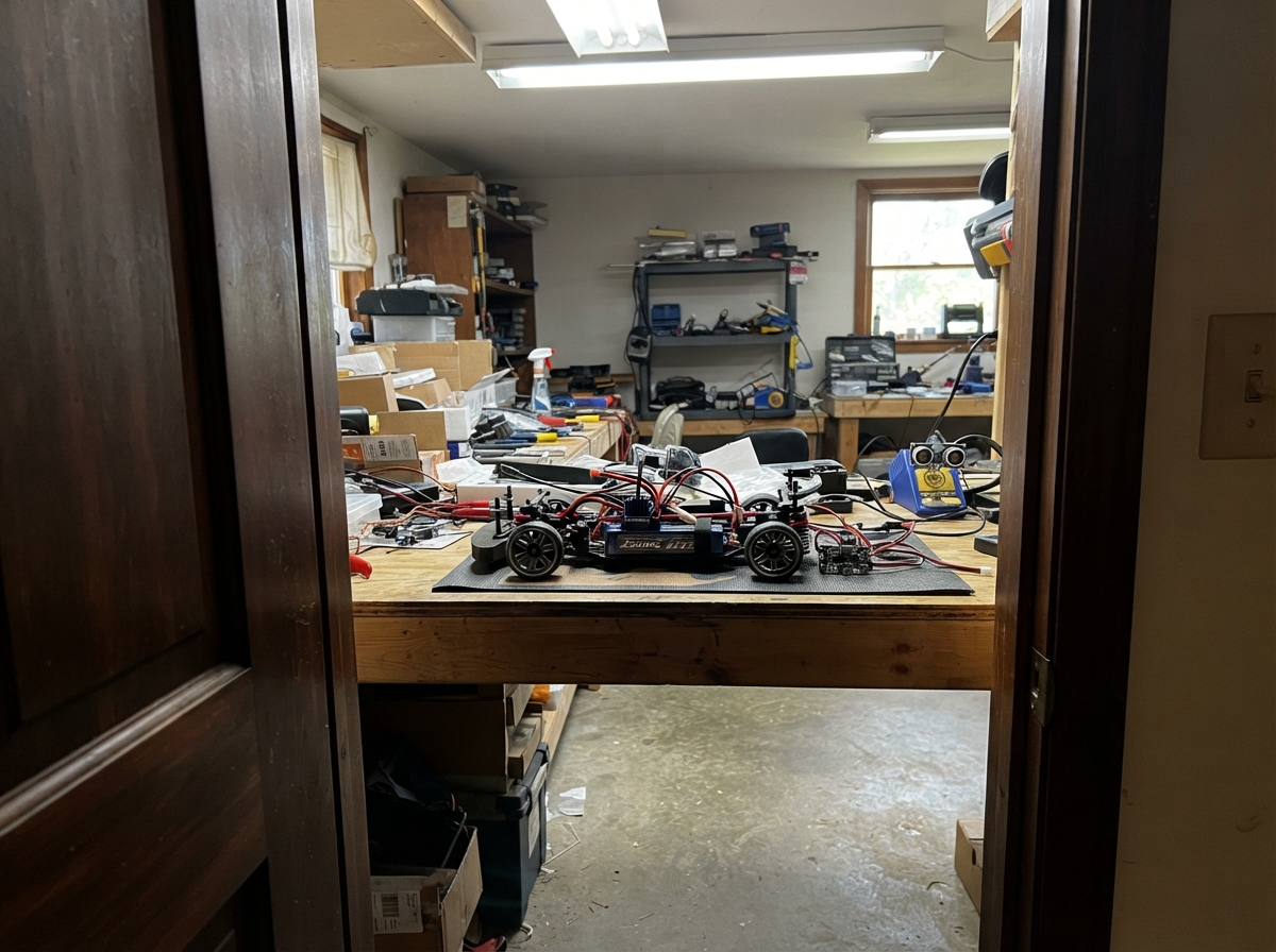
This guide builds an autonomous drift car that navigates obstacles and executes controlled turns using onboard sensors and an ESP32 microcontroller. The car combines a brushless motor, metal-gear steering servo, and 7.4 V LiPo power with an MPU-6050 gyroscope and HC-SR04P ultrasonic sensor to detect obstacles and measure rotation rates, enabling autonomous obstacle avoidance and drift maneuvers.
The guide provides a complete wiring diagram, detailed parts list, and ready-to-flash firmware that implements state-based autonomous driving logic. Assembly steps cover mounting the drivetrain and steering, positioning sensors for forward detection, building the battery power distribution with proper switching and regulation, and safety checks before operation.
Wiring diagram

Gather all the parts
Assemble it in 7 steps
1. Mount the drivetrain
Bolt the 13.5T brushless motor (drive_motor) into the motor mount and mesh its small gear with the chassis spur gear. Mount the 30 A ESC (esc_30a) where air can reach it, then connect its three motor leads to A, B, and C on the motor.
- With the battery disconnected, turn the rear wheels by hand. They should turn freely with only a small amount of gear movement before the motor turns.
- Keep fingers, loose hair, and wires away from the spinning gears; the wheels can start unexpectedly during testing.
2. Fit the steering parts
Screw the metal-gear steering servo (steering_servo) into the chassis, attach its arm with the wheels held straight, then connect the steering link. Mount the ESP32 board where it cannot touch the metal chassis or moving steering parts.
- Leave the servo-arm screw accessible so you can center the wheels later.
- Do not force the steering past its mechanical stops; a stalled servo can overheat or strip gears.
3. Mount the sensors facing forward
Fix the ultrasonic sensor (front_sonar) at the front bumper with its two round openings facing straight ahead. Stick the MPU-6050 board (imu_mpu6050) flat near the car’s center, with its printed top facing upward and its front pointing toward the front bumper.
- Keep the ultrasonic sensor clear of the body shell so it can hear its own sound echo.
- Do not mount the sensor boards where a wheel, driveshaft, or steering link can strike them.
4. Build the switched battery power leads
With the battery unplugged, connect battery BAT+ to arming_switch BAT+ IN and battery BAT- to arming_switch BAT- IN. Connect the switch LOAD+ OUT to ESC VCC, MP1584 VIN, and UBEC VIN+. Connect the switch LOAD- OUT, ESC GND, MP1584 GND, and UBEC VIN- together as the shared ground return.
- Use suitably thick RC power wire and insulated connectors for the battery, ESC, switch, and both regulator input leads.
- A 2S LiPo can deliver enough current to melt wires or start a fire if positive and negative touch. Build and inspect these leads with the battery disconnected.
5. Set the ESP32 and steering power
Before connecting the ESP32, use a meter to adjust MP1584 VOUT to exactly 5.0 V. Connect MP1584 VOUT to ESP32 VIN/5V and its GND to ESP32 GND. Connect UBEC VOUT+ to steering servo VCC and UBEC VOUT- to steering servo GND. Join the servo ground to the ESP32 GND so the steering signal has the same reference.
- The steering servo usually has red for VCC, brown or black for GND, and orange, yellow, or white for SIG.
- Do not connect the raw 7.4 V battery to the ESP32 or steering servo; it can damage them. Do not connect the ESC’s 5 V receiver lead to this circuit because the separate UBEC already powers the servo.
6. Wire the control and sensor leads
Connect ESC PWM to ESP32 GPIO25 (throttle signal). Connect steering servo SIG to GPIO33 (steering signal). Connect MPU-6050 VIN to 3V3, GND to GND, SDA to GPIO21, and SCL to GPIO22. Connect ultrasonic VCC to 3V3, GND to GND, TRIG to GPIO27, and ECHO to GPIO26.
- Use short signal wires and secure them to the chassis so vibration cannot pull them loose.
- Make sure the ultrasonic module is the 3.3 V HC-SR04P or HC-SR04-33 version; an ordinary 5 V HC-SR04 can send a damaging 5 V signal into the ESP32.
7. Check it with the wheels off the floor
Place the chassis on a stand so all four wheels are clear. Turn on the arming switch, plug the ESP32 into USB, and use Deploy. Keep the car pointed into an empty area when you first test the distance response.
- If the car moves when it should be still, turn off the arming switch immediately and check the ESC’s neutral setting before trying again.
- Never hold the car by hand during a powered test; a spinning wheel can injure you or pull the car from your grip.
Review all connections
1. Connections between "lipo_2s" and "ESP32"
2. Connections between "arming_switch" and "ESP32"
3. Connections between "esc_30a" and "ESP32"
4. Connections between "mp1584_5v" and "ESP32"
5. Connections between "servo_ubec" and "ESP32"
6. Connections between "steering_servo" and "ESP32"
7. Connections between "imu_mpu6050" and "ESP32"
8. Connections between "front_sonar" and "ESP32"
Deploy the firmware
#include <Arduino.h>
#include <Wire.h>
#include <ESP32Servo.h>
#include <MPU6050.h>


// Hoisted type definitions
enum DriveState { CRUISE, BRAKE, TURN };


// Forward declarations
void setOutputs(int escPulse, int steeringPulse);
void stopCar();
uint16_t readDistanceCm();
int16_t yawRateRaw();

constexpr int ESC_SIGNAL_PIN = 25;
constexpr int STEERING_SIGNAL_PIN = 33;
constexpr int SONAR_TRIG_PIN = 27;
constexpr int SONAR_ECHO_PIN = 26;
constexpr int I2C_SDA_PIN = 21;
constexpr int I2C_SCL_PIN = 22;

// Conservative receiver-style commands. Confirm ESC neutral and servo travel with
// the chassis raised before placing it on the ground.
constexpr int ESC_NEUTRAL_US = 1500;
constexpr int ESC_CRUISE_US = 1565;
constexpr int ESC_BRAKE_US = 1450;
constexpr int STEER_CENTER_US = 1500;
constexpr int STEER_LEFT_US = 1270;
constexpr int STEER_RIGHT_US = 1730;
constexpr uint16_t OBSTACLE_CM = 80;
constexpr uint32_t SENSOR_INTERVAL_MS = 70;
constexpr uint32_t BRAKE_TIME_MS = 250;
constexpr uint32_t TURN_TIME_MS = 750;
constexpr int16_t MAX_TURN_RATE_RAW = 18000;


Servo esc;
Servo steering;
MPU6050 imu;
DriveState driveState = CRUISE;
uint32_t stateStartedAt = 0;
uint32_t lastSensorAt = 0;
bool turnLeft = true;

void setOutputs(int escPulse, int steeringPulse) {
  esc.writeMicroseconds(escPulse);
  steering.writeMicroseconds(steeringPulse);
}

void stopCar() {
  setOutputs(ESC_NEUTRAL_US, STEER_CENTER_US);
}

uint16_t readDistanceCm() {
  digitalWrite(SONAR_TRIG_PIN, LOW);
  delayMicroseconds(2);
  digitalWrite(SONAR_TRIG_PIN, HIGH);
  delayMicroseconds(10);
  digitalWrite(SONAR_TRIG_PIN, LOW);

  const unsigned long echoUs = pulseIn(SONAR_ECHO_PIN, HIGH, 24000);
  return echoUs == 0 ? 400 : static_cast<uint16_t>(echoUs / 58UL);
}

int16_t yawRateRaw() {
  int16_t gx, gy, gz;
  imu.getRotation(&gx, &gy, &gz);
  return gz;
}

void setup() {
  Serial.begin(115200);
  pinMode(SONAR_TRIG_PIN, OUTPUT);
  pinMode(SONAR_ECHO_PIN, INPUT);
  digitalWrite(SONAR_TRIG_PIN, LOW);

  esc.setPeriodHertz(50);
  steering.setPeriodHertz(50);
  esc.attach(ESC_SIGNAL_PIN, 1000, 2000);
  steering.attach(STEERING_SIGNAL_PIN, 1000, 2000);
  stopCar();
  delay(3000); // Gives the ESC a neutral throttle command while it starts.

  Wire.begin(I2C_SDA_PIN, I2C_SCL_PIN);
  imu.initialize();
  if (!imu.testConnection()) {
    Serial.println("MPU-6050 not found; drive is disabled.");
    while (true) {
      stopCar();
      delay(100);
    }
  }

  stateStartedAt = millis();
  Serial.println("Autonomous drift prototype ready.");
}

void loop() {
  const uint32_t now = millis();

  if (driveState == CRUISE) {
    setOutputs(ESC_CRUISE_US, STEER_CENTER_US);
    if (now - lastSensorAt >= SENSOR_INTERVAL_MS) {
      lastSensorAt = now;
      const uint16_t distanceCm = readDistanceCm();
      Serial.printf("Distance: %u cm\n", distanceCm);
      if (distanceCm < OBSTACLE_CM) {
        driveState = BRAKE;
        stateStartedAt = now;
      }
    }
    return;
  }

  if (driveState == BRAKE) {
    setOutputs(ESC_BRAKE_US, STEER_CENTER_US);
    if (now - stateStartedAt >= BRAKE_TIME_MS) {
      turnLeft = !turnLeft;
      driveState = TURN;
      stateStartedAt = now;
    }
    return;
  }

  const int steeringPulse = turnLeft ? STEER_LEFT_US : STEER_RIGHT_US;
  const int throttlePulse = abs(yawRateRaw()) > MAX_TURN_RATE_RAW
                              ? ESC_NEUTRAL_US
                              : ESC_CRUISE_US;
  setOutputs(throttlePulse, steeringPulse);

  if (now - stateStartedAt >= TURN_TIME_MS) {
    driveState = CRUISE;
    stateStartedAt = now;
  }
}
Remix this project
Make it yours in one click
Open a full copy of this project in your own Schematik workspace — diagram, code, parts, and assembly steps included. Swap the sensor, add features, or redesign the whole thing with AI. The author's original stays untouched.