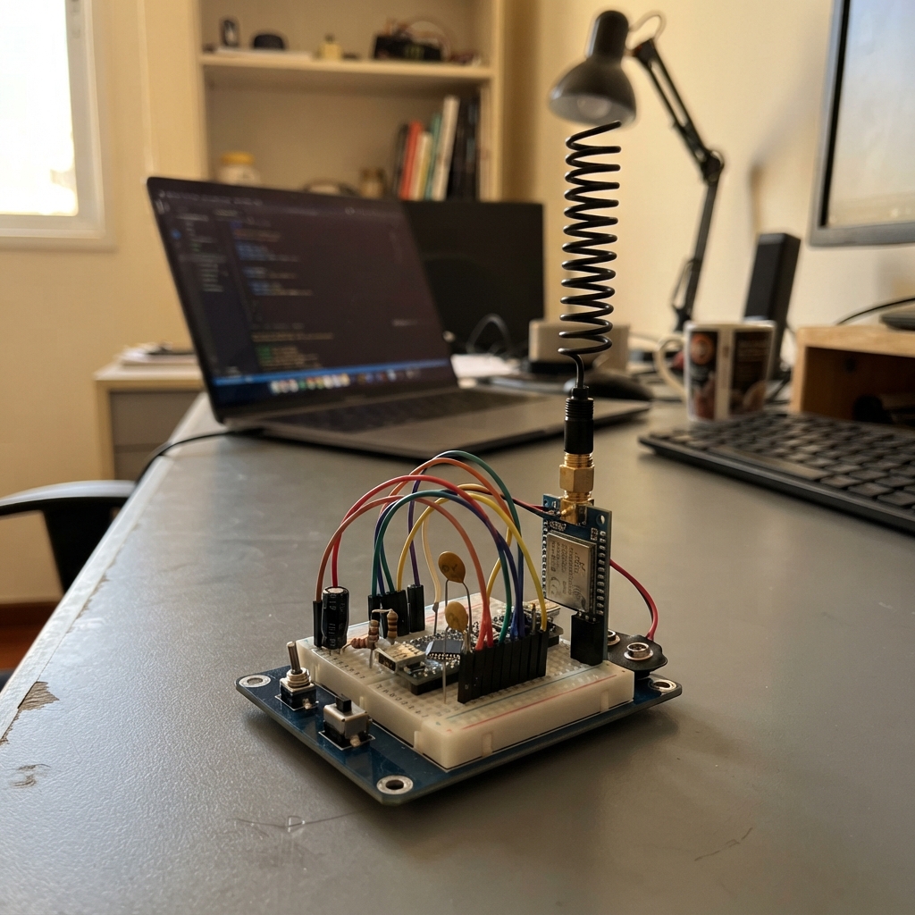
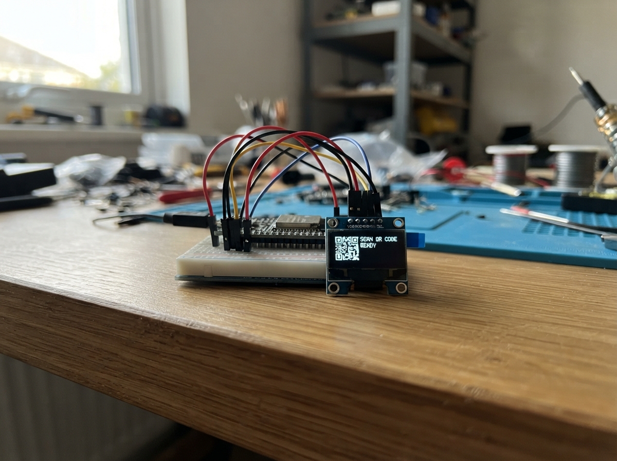
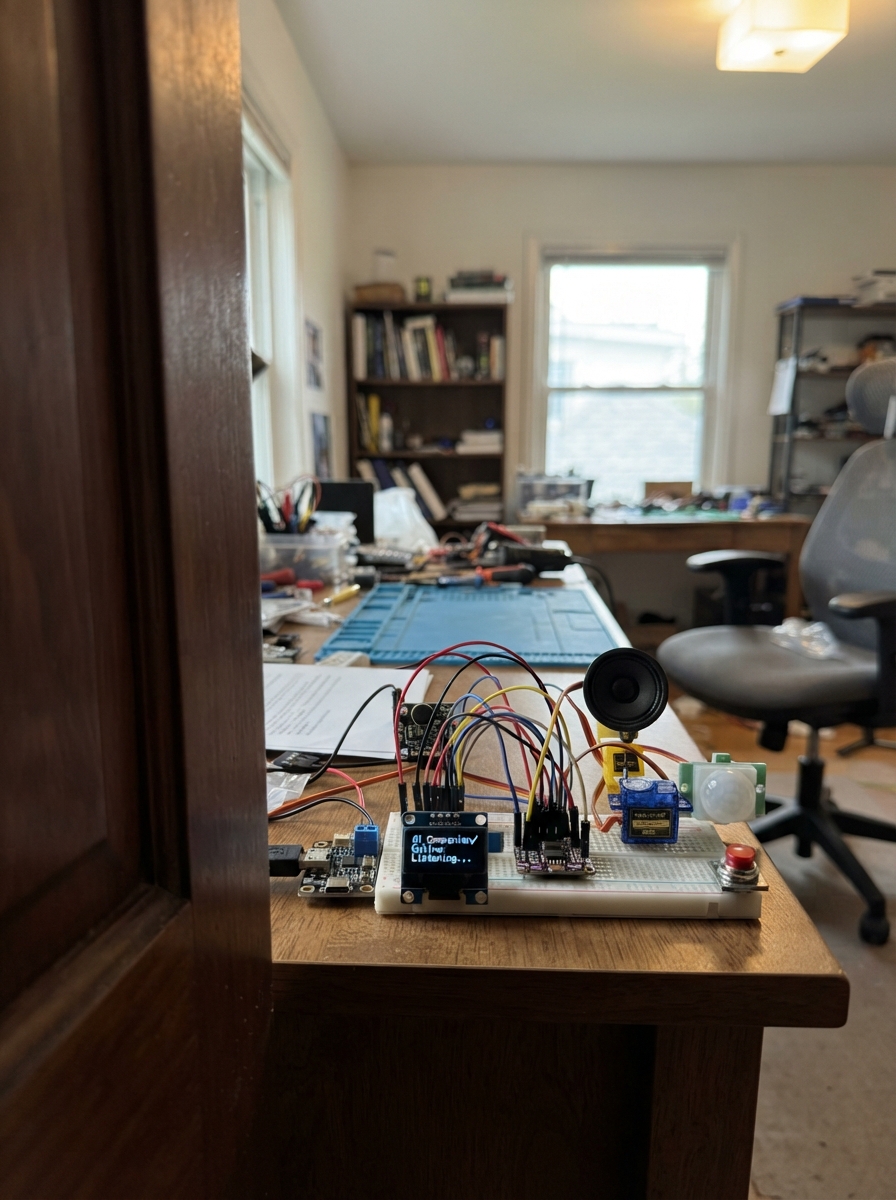
Community project
Autonomous Rowing GPS Tracker
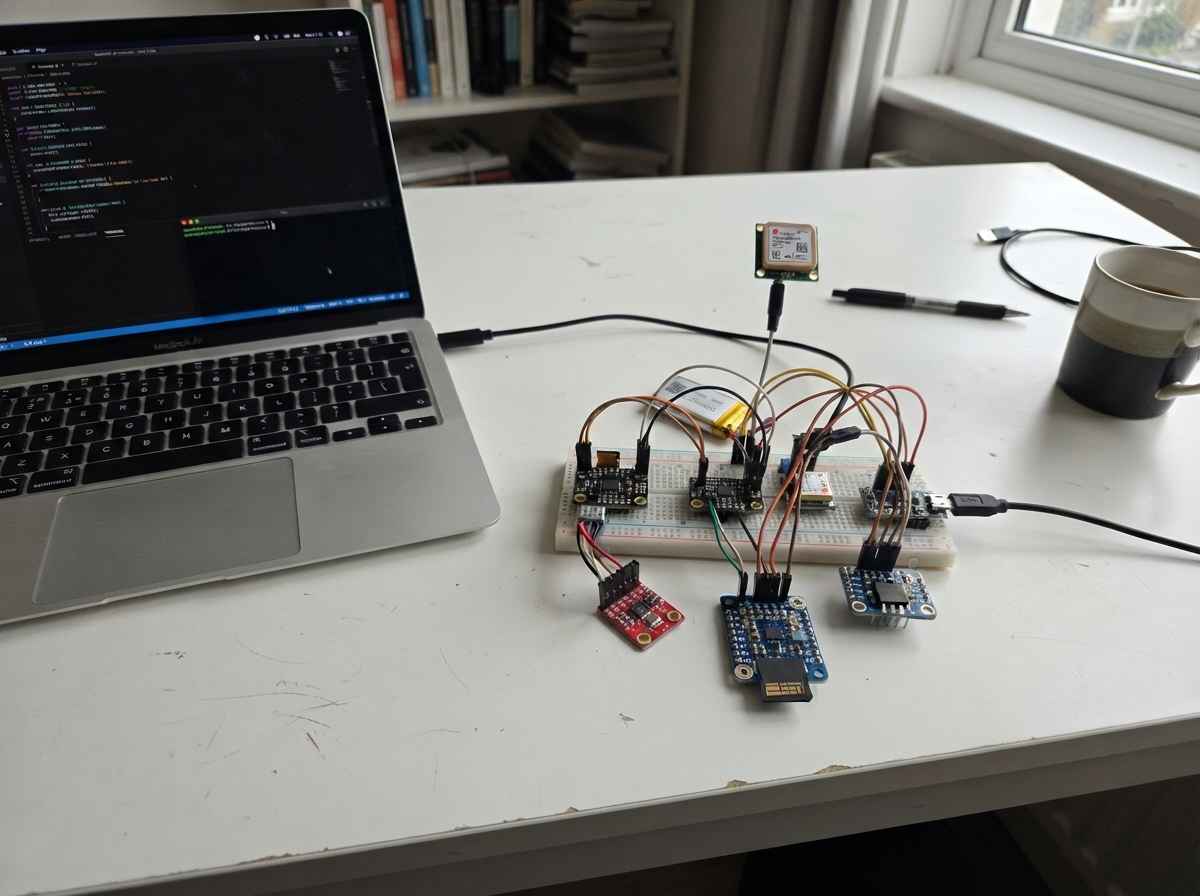
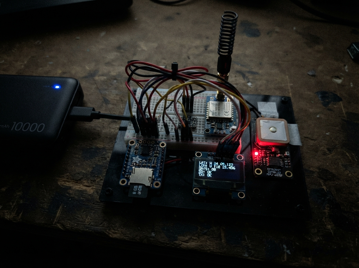
This project builds a GPS-enabled rowing tracker that records position, motion, and performance data during rowing sessions. The ESP32 collects data from a u-blox NEO-M8N GPS module, a 6-axis IMU sensor, and battery monitoring through an ADS1115 ADC, then logs everything to a microSD card for later analysis. The system includes a long-range radio module for potential shore communication and uses a protected lithium battery with charging and power management.
This guide provides a complete parts list, wiring diagram, power distribution schematic, and step-by-step assembly instructions for building the tracker on a breadboard. You'll learn how to integrate multiple I2C and SPI sensors, configure the ESP32 firmware for GPS and IMU data collection, and validate all subsystems before final deployment on the water.
Wiring diagram
Gather all the parts
Assemble it in 10 steps
1. Separar peças e revisar antes de energizar
Este é um protótipo de engenharia, não uma unidade liberada para água. Use a Super Mini ESP32-C3, o breakout GPS com entrada 3,3 V comprovada, SEN0142 MPU-6050, módulo ADS1115, MCP23017 e adaptador SD exclusivamente 3,3 V. Separe os componentes sobre bancada seca. O cartão vai no encaixe do adaptador; suas ligações no desenho são internas ao encaixe.
- Não substituir o leitor SD por um módulo de entrada 5 V sem revisar o circuito; pode falhar em 3,3 V ou aplicar tensão excessiva aos sinais.
2. Montar a alimentação fora da protoboard
Use pack pronto 1S protegido, nunca células soltas em paralelo. Positivo/negativo do pack vão a B+/B- do TP4056. OUT+ passa pelo fusível 2 A e pelo conector removível jbat até VIN+ do boost. OUT- é o terra do sistema. Não una B- a OUT- por outro fio, pois isso contorna a proteção do carregador. Use fios de potência curtos e conexões isoladas; não conduza corrente da bateria por contatos frágeis de protoboard.
- A polaridade dos conectores de bateria varia entre fabricantes; confira com multímetro antes de encaixar.
- Para recarregar: separar jbat e só então ligar USB ao TP4056. Não carregar em caixa fechada, molhada ou sem supervisão.
3. Ajustar e medir os dois barramentos
Com a eletrônica ainda desconectada, ligue o ânodo do 1N5819 ao VOUT+ do boost e o cátodo com faixa ao barramento 5 V. Ajuste o boost para obter cerca de 5,0 V depois do diodo sob carga. Nunca permita mais de 5,5 V, inclusive sem carga. O 5 V alimenta o pino 5V da Super Mini, o rádio e VIN do módulo AMS1117. A saída do AMS1117 deve medir 3,3 V e alimenta os periféricos. Não ligue essa saída ao pino 3V3 da Super Mini: são dois reguladores separados com terra comum.
- Somente prossiga após testar 5 V e 3,3 V com multímetro e carga. O E220 precisa de pelo menos 5,0 V para garantir a potência nominal.
- Retire jbat antes de conectar USB ao ESP32: o diodo não impede o boost de enviar energia à porta USB do computador.
4. Montar o barramento de sensores
Ligue SDA de MPU-6050, ADS1115 e MCP23017 a GPIO0 (dados). SCL de todos vai a GPIO1 (relógio). Alimente todos em EXT3V3 e una seus terras ao GND. MCP A0/A1/A2 no GND seleciona 0x20; RESET sobe a EXT3V3 pelo resistor de 10 kΩ. ADS ADDR vai a GND para 0x48; IMU usa 0x68. Os resistores de 4,7 kΩ puxam SDA/SCL para EXT3V3; confira a resistência equivalente com os pull-ups já presentes nos módulos.
- Use fios de sinal até cerca de 15 cm. Confirme que nenhum pull-up termina em 5 V e que a resistência equivalente de cada linha não fica abaixo de aproximadamente 1 kΩ.
5. Medir a bateria pelo divisor
Ligue um resistor de 100 kΩ entre jbat.OUT e AIN0 do ADS1115. Outro de 100 kΩ vai de AIN0 ao GND. O capacitor de 100 nF fica entre AIN0 e GND. Assim, a entrada recebe metade da tensão da bateria. A medição é em milivolts; não é uma porcentagem de carga.
6. Conectar GPS e sua antena
GPS TX vai a GPIO20 (recepção do ESP32); GPS RX vai a GPIO21 (configuração enviada pelo ESP32). GPS VCC recebe EXT3V3 e GND recebe o terra comum. Conecte a antena L1 fornecida para o breakout ao conector RF. Confirme antes da compra que a placa, não só o chip, funciona na entrada escolhida de 3,3 V.
- O GPS proposto é NEO-M8N genuíno em modo apenas GPS. Não trocar por NEO-6M de 5 Hz nem ligar um conector de bússola como se fosse UART.
7. Conectar rádio e antena antes de ligar
E220 VCC recebe 5 V e GND recebe terra comum. TXD vai a GPIO3 (dados recebidos pelo ESP32) e RXD a GPIO10 (dados enviados pelo ESP32). No MCP23017: GPA0 vai a M0, GPA1 a M1 e GPA2 a AUX. Cada M0/M1 tem resistor de 10 kΩ ao GND. O capacitor de 470 µF e o de 100 nF ficam junto a VCC/GND do rádio. Monte a antena SMA 915 MHz de 50 ohms.
- Não ligar UART TTL de 5 V. Não alimentar o rádio pelo pino 3V3 da Super Mini. Não energizar sem antena.
- Transmissão vem desabilitada no firmware para revisão de antena, alimentação e condições regulatórias. Homologação Anatel permanece pendente.
8. Conectar armazenamento
SD CLK vai a GPIO4 (relógio); MISO a GPIO5 (leitura); MOSI a GPIO6 (escrita); CS a GPIO7 (seleção). Alimente o adaptador em EXT3V3, nunca em 5 V. Ponha o capacitor de 220 µF junto ao leitor. Insira cartão microSDHC genuíno de 8 GB com uma partição FAT32, com tudo desligado.
- O capacitor de 100 µF estabiliza EXT3V3. O módulo regulador precisa ter os capacitores locais de entrada/saída previstos pelo fabricante; não usar o chip AMS1117 solto como se fosse módulo pronto.
9. Validar em bancada antes de fechar
Confira fio por fio com a tabela e meça as tensões. Com jbat separado, conecte USB à Super Mini para gravar o firmware. Para ensaio autônomo, retire USB e reconecte jbat. Verifique o arquivo após desligar: CRC, continuidade de sequências, épocas GPS de 100 ms e amostras IMU. Execute os testes descritos em include/docs/TESTES.md. Não aprove o treino se faltar cartão, GPS, bateria ou dados.
10. Fixar e proteger após os testes
Protoboard serve apenas para bancada. Para o barco, fixe os módulos em suporte e use ligações soldadas ou conectores travados em placa perfurada universal, sem PCB própria. Fixe a IMU rigidamente e anote a orientação. Use caixa não metálica estanque com tampa vedada, antena GPS voltada ao céu e LoRa afastada do corpo e do boost; prenda atrás do último remador com retenção secundária. Não deixar cabos nem botões expostos durante o treino.
- Não usar protoboard solta na água. Estanqueidade, condensação, aquecimento, flutuação e fixação precisam de ensaio separado, sem a bateria dentro.
- A retirada abrupta da alimentação pode perder o último segundo e corromper FAT32. Faça cópia dos arquivos após cada treino. Não é equipamento de segurança ou navegação certificada.
Review all connections
1. Connections between "battery" and "ESP32"
2. Connections between "charger" and "ESP32"
3. Connections between "fuse" and "ESP32"
4. Connections between "jbat" and "ESP32"
5. Connections between "boost" and "ESP32"
6. Connections between "diode" and "ESP32"
7. Connections between "ldo" and "ESP32"
8. Connections between "gps" and "ESP32"
9. Connections between "imu" and "ESP32"
10. Connections between "adc" and "ESP32"
11. Connections between "io" and "ESP32"
12. Connections between "sd" and "ESP32"
13. Connections between "radio" and "ESP32"
14. Connections between "rrst" and "ESP32"
15. Connections between "rm0" and "ESP32"
16. Connections between "rm1" and "ESP32"
17. Connections between "rbat1" and "ESP32"
18. Connections between "rbat2" and "ESP32"
19. Connections between "cdiv" and "ESP32"
20. Connections between "rsda" and "ESP32"
21. Connections between "rscl" and "ESP32"
22. Connections between "antlora" and "ESP32"
23. Connections between "antgps" and "ESP32"
24. Connections between "cboost" and "ESP32"
25. Connections between "cradio" and "ESP32"
26. Connections between "csd" and "ESP32"
27. Connections between "crail" and "ESP32"
28. Connections between "cgps" and "ESP32"
29. Connections between "cimu" and "ESP32"
30. Connections between "cio" and "ESP32"
31. Connections between "cadc" and "ESP32"
32. Connections between "crf" and "ESP32"
33. Connections between "card" and "ESP32"
34. Connections between "usbcharge" and "ESP32"
Deploy the firmware
#include <Arduino.h>
#include <Wire.h>
#include <SPI.h>
#include <SD.h>
#include <HWCDC.h>
#include <Preferences.h>
#include <Adafruit_MCP23X17.h>
#include <Adafruit_ADS1X15.h>
#include <Adafruit_MPU6050.h>
#include <SparkFun_u-blox_GNSS_Arduino_Library.h>
#include <esp_timer.h>
#include <esp_sleep.h>
#include "protocol.h"
#include "shore_bridge.h"
// Wiring revision A checked: UART0 20/21, UART1 3/10, I2C 0/1, SPI 4/5/6/7.

// Do not use Serial: UART0 belongs exclusively to GPS. USB console is explicit.
HWCDC console;
HardwareSerial gpsPort(0),radioPort(1);
SFE_UBLOX_GNSS gps;
Adafruit_MCP23X17 io;
Adafruit_ADS1115 adc;
Adafruit_MPU6050 imu;
QueueHandle_t logQueue;
remo::Data state{};
uint64_t sessionId,started;
uint32_t recordSeq=0,radioSeq=0,lastGps=0,lastImu=0,lastAck=0;
uint32_t prevTow=0,rateStart=0,rateCount=0,rateBad=0;
bool haveTow=false,gpsDetected=false,gpsConfigured=false,imuReady=false;
bool ioReady=false,adcReady=false,radioReady=false,rateOK=false;
float prevSpeed=0;
bool prevGood=false;
volatile bool sdReady=false,shutdownRequested=false,shutdownDone=false;
volatile uint32_t sdErrors=0;
uint32_t lowCount=0,lastBatteryValid=0;
constexpr bool RADIO_TX_ENABLED=false; // Enable only after antenna + legal/RF review.
constexpr uint8_t IO_M0=0,IO_M1=1,IO_AUX=2;
constexpr uint8_t RADIO_CHANNEL=65; // 915.125 MHz = 850.125 + 65
constexpr uint32_t RADIO_INTERVAL_MS=5000; // one 142-byte frame / 5 s
uint64_t nowms(){return (uint64_t)esp_timer_get_time()/1000;}

void refresh() {
 uint32_t now=millis();
 if(!lastBatteryValid || now-lastBatteryValid>3000)state.battery_mv=UINT16_MAX;
 bool freshGps=lastGps && now-lastGps<500;
 state.gps_age_ms=lastGps?now-lastGps:UINT32_MAX;
 state.imu_age_ms=lastImu?now-lastImu:UINT32_MAX;
 state.sd_errors=sdErrors;
 state.flags=(freshGps && state.fix>=3 && prevGood ? remo::GPS_OK:0)
 |(imuReady && state.imu_age_ms<100?remo::IMU_OK:0)
 |(sdReady?remo::SD_OK:0)|(radioReady?remo::RADIO_OK:0)
 |(rateOK && freshGps?remo::GPS_10HZ:0)|(lowCount>=3?remo::LOW_BAT:0)
 |(state.queue_drops?remo::QUEUE_LOSS:0)|(state.utc_valid==7?remo::UTC_OK:0)
 |(gpsConfigured?remo::GPS_CONFIG:0)|(adcReady && state.battery_mv!=UINT16_MAX?remo::ADC_OK:0)
 |(lastAck && now-lastAck<20000?remo::ACK_RECENT:0);
 if(ioReady && !io.digitalRead(IO_AUX))state.flags|=remo::RADIO_BUSY;
}
remo::Frame frame(uint8_t kind,uint32_t seq) {
 refresh(); remo::Frame f{};
 f.header={remo::MAGIC,remo::VERSION,kind,sizeof(f),sessionId,seq,nowms()-started};
 f.data=state; remo::seal(f); return f;
}
void logSample(uint8_t kind) {
 remo::Frame f=frame(kind,recordSeq++);
 if(xQueueSend(logQueue,&f,0)!=pdPASS)state.queue_drops++;
}
void pvt(UBX_NAV_PVT_data_t *p) {
 uint32_t now=millis();
 bool good=p->flags.bits.gnssFixOK && p->fixType==3 && !p->flags3.bits.invalidLlh
 && p->hAcc<=5000 && p->sAcc<=1000 && p->gSpeed>=0;
 if(haveTow) {
  uint32_t dt=(p->iTOW+604800000UL-prevTow)%604800000UL;
  if(dt!=100)rateBad++;
  // Generic distance only: trapezoidal integration of GNSS ground speed.
  // Never bridge loss of fix or time gaps; no rowing-specific model.
  if(good && prevGood && dt>0 && dt<=200)
   state.distance_m+=(prevSpeed+p->gSpeed)*0.5f*dt/1000000.0f;
 }
 prevTow=p->iTOW;haveTow=true;prevSpeed=p->gSpeed;prevGood=good;
 lastGps=now;rateCount++;
 state.itow_ms=p->iTOW;state.lat_e7=p->lat;state.lon_e7=p->lon;
 state.alt_msl_mm=p->hMSL;state.speed_mm_s=p->gSpeed;
 state.hacc_mm=p->hAcc;state.sacc_mm_s=p->sAcc;state.pdop_centi=p->pDOP;
 state.fix=p->fixType;state.satellites=p->numSV;
 state.utc_valid=p->valid.all&7;state.year=p->year;state.month=p->month;
 state.day=p->day;state.hour=p->hour;state.minute=p->min;state.second=p->sec;
 state.utc_nano=p->nano; logSample(remo::GPS);
}
bool auxReady(uint32_t timeout=1500) {
 uint32_t t=millis(),highAt=0;
 do {
  if(io.digitalRead(IO_AUX)) { if(!highAt)highAt=millis(); if(millis()-highAt>=3)return true; }
  else highAt=0;
  delay(1);
 }while(millis()-t<timeout);return false;
}
bool radioInit() {
 if(!ioReady)return false;
 io.digitalWrite(IO_M0,LOW);io.digitalWrite(IO_M1,LOW);
 io.pinMode(IO_M0,OUTPUT);io.pinMode(IO_M1,OUTPUT);io.pinMode(IO_AUX,INPUT);
 radioPort.setTxBufferSize(512);
 radioPort.begin(9600,SERIAL_8N1,3,10);
 delay(100);
 if(!auxReady())return false;
 io.writeGPIOA(3);delay(10);if(!auxReady())return false;
 while(radioPort.available())radioPort.read();
 // Temporary registers: address 0, 9600 8N1, air 2.4k, 200B packets,
 // 22dBm, channel 65, transparent mode, no appended RSSI, key zero.
 const uint8_t cmd[]={0xC2,0,8,0,0,0x62,0,RADIO_CHANNEL,0,0,0};
 radioPort.write(cmd,sizeof(cmd));
 uint8_t reply[11]{};size_t n=0;uint32_t t=millis();
 while(n<sizeof(reply)&&millis()-t<1000) {
  if(radioPort.available())reply[n++]=radioPort.read();else delay(1);
 }
 bool ok=n==11 && reply[0]==0xC1 && reply[1]==0 && reply[2]==8;
 for(int i=3;i<9;i++)ok=ok && reply[i]==cmd[i];
 // Keys are write-only and read back zero; configured zero explicitly.
 if(!auxReady())ok=false;
 io.writeGPIOA(0);delay(10);return auxReady()&&ok;
}
bool gpsInit() {
 // Autobaud without nonvolatile GPS writes. A genuine cold M8N normally uses 9600.
 for(uint32_t baud: {9600UL,38400UL,115200UL}) {
  gpsPort.begin(baud,SERIAL_8N1,20,21);delay(50);
  if(gps.begin(gpsPort,400)){gpsDetected=true;break;}
  gpsPort.end();
 }
 if(!gpsDetected)return false;
 gps.setSerialRate(115200);delay(100);gpsPort.updateBaudRate(115200);delay(50);
 if(!gps.begin(gpsPort,700))return false;
 bool ok=gps.setUART1Output(COM_TYPE_UBX,500);
 // Limit M8N to one constellation to stay within its documented 10Hz rate.
 for(auto id: {SFE_UBLOX_GNSS_ID_GLONASS,SFE_UBLOX_GNSS_ID_BEIDOU,
 SFE_UBLOX_GNSS_ID_GALILEO,SFE_UBLOX_GNSS_ID_SBAS,SFE_UBLOX_GNSS_ID_QZSS,
 SFE_UBLOX_GNSS_ID_IMES}) {
  // Unsupported constellations on an old M8 may NAK. Only disabling supported ones is needed.
  gps.enableGNSS(false,id,400);
 }
 ok=gps.enableGNSS(true,SFE_UBLOX_GNSS_ID_GPS,500)&&ok;
 ok=gps.setNavigationFrequency(10,700)&&ok;
 ok=(gps.getMeasurementRate(500)==100)&&ok;
 ok=(gps.getNavigationRate(500)==1)&&ok;
 ok=gps.setAutoPVTcallbackPtr(pvt,700)&&ok;
 console.printf("GPS configuration: %s. 10 Hz ainda exige medicao de iTOW.\n",ok?"ACK+readback OK":"FALHOU");
 return ok;
}
void receiveAck() {
 static uint8_t buf[sizeof(remo::Frame)];static size_t n=0;
 while(radioPort.available()) {
  uint8_t b=radioPort.read();
  if(n==0 && b!=0x5A)continue;
  if(n==1 && b!=0xA5){n=(b==0x5A)?1:0;continue;}
  buf[n++]=b;
  if(n==sizeof(buf)) {
   remo::Frame f;memcpy(&f,buf,sizeof(f));n=0;
   if(remo::valid(f)&&f.header.kind==remo::ACK&&f.header.session==sessionId
    &&radioSeq>0&&f.header.sequence==radioSeq-1)lastAck=millis();
  }
 }
}
void logger(void*) {
 File file;char path[48];uint32_t part=0,lastMount=0,lastFlush=0;
 uint64_t bytes=0;
 for(;;) {
  if(shutdownDone){vTaskDelay(pdMS_TO_TICKS(50));continue;}
  if(!sdReady && millis()-lastMount>=2000 && !shutdownRequested) {
   lastMount=millis();
   if(file)file.close();SD.end();
   if(SD.begin(7,SPI,4000000)) {
    snprintf(path,sizeof(path),"/R%08lX%08lX_%03lu.bin",(unsigned long)(sessionId>>32),(unsigned long)sessionId,(unsigned long)part++);
    file=SD.open(path,FILE_WRITE);sdReady=(bool)file;bytes=0;
    if(sdReady)console.printf("SD: %s\n",path);
   }
   if(!sdReady)sdErrors++;
  }
  remo::Frame f;
  if(xQueueReceive(logQueue,&f,pdMS_TO_TICKS(5))==pdPASS) {
   if(sdReady) {
    if(file.write((uint8_t*)&f,sizeof(f))!=sizeof(f)) {sdReady=false;sdErrors++;file.close();}
    else bytes+=sizeof(f);
   }else sdErrors++; // Explicit lost-record counter. No claim of storage with broken card.
  }
  if(sdReady && millis()-lastFlush>=1000) {
   file.flush();lastFlush=millis();
   // flush() returns void in Arduino SD. Write success cannot certify media integrity.
   if(bytes>=256ULL*1024*1024) {file.close();sdReady=false;}
  }
  if(shutdownRequested && uxQueueMessagesWaiting(logQueue)==0) {
   if(file){file.flush();file.close();}sdReady=false;shutdownDone=true;
  }
 }
}
void setup() {
 console.begin(115200);delay(200);
 started=nowms();
 Preferences prefs;prefs.begin("remo",false);
 uint32_t boot=prefs.getUInt("boot",0)+1;prefs.putUInt("boot",boot);prefs.end();
 sessionId=((ESP.getEfuseMac()&0xffffffffULL)<<32)|boot;
 state.battery_mv=UINT16_MAX;
 state.ax=state.ay=state.az=state.gx=state.gy=state.gz=state.temperature_c=NAN;
 logQueue=xQueueCreate(512,sizeof(remo::Frame));
 if(!logQueue){console.println("ERRO: sem buffer de gravacao");while(true)delay(1000);}
 Wire.begin(0,1,400000);Wire.setTimeOut(20);
 ioReady=io.begin_I2C(0x20,&Wire);
 adcReady=adc.begin(0x48,&Wire);
 if(adcReady){adc.setGain(GAIN_ONE);adc.setDataRate(RATE_ADS1115_128SPS);}
 imuReady=imu.begin(0x68,&Wire);
 if(imuReady) {
  imu.setAccelerometerRange(MPU6050_RANGE_4_G);imu.setGyroRange(MPU6050_RANGE_500_DEG);
  imu.setFilterBandwidth(MPU6050_BAND_21_HZ);imu.setSampleRateDivisor(19);
 }
 radioReady=radioInit();
 gpsPort.setRxBufferSize(8192);
 gpsConfigured=gpsInit();rateStart=millis();
 SPI.begin(4,5,6,7);
 if(xTaskCreate(logger,"sdwriter",6144,nullptr,1,nullptr)!=pdPASS) {
  console.println("ERRO: tarefa SD");while(true)delay(1000);
 }
 console.printf("sessao=%016llX frame=%u bytes radio TX=%s\n",sessionId,sizeof(remo::Frame),RADIO_TX_ENABLED?"ON":"OFF seguro");
}
void loop() {
 static uint32_t imuAt=0,healthAt=0,radioAt=0,adcAt=0;
 static bool adcPending=false;
 uint32_t now=millis();
 if(shutdownRequested){
  if(shutdownDone) {
   if(ioReady){io.writeGPIOA(3);delay(20);}
   console.println("Bateria baixa: SD fechado. Desconecte a bateria apos o treino.");
   console.flush();esp_deep_sleep_start();
  }
  delay(20);return;
 }
 if(gpsDetected){gps.checkUblox();gps.checkCallbacks();}
 if(imuReady && now-imuAt>=20) {
  if(imuAt && now-imuAt>=40)state.imu_missed+=(now-imuAt)/20-1;
  imuAt=now;sensors_event_t a,g,t;
  if(imu.getEvent(&a,&g,&t)) {
   state.ax=a.acceleration.x;state.ay=a.acceleration.y;state.az=a.acceleration.z;
   state.gx=g.gyro.x;state.gy=g.gyro.y;state.gz=g.gyro.z;state.temperature_c=t.temperature;
   lastImu=now;logSample(remo::IMU);
  }else imuReady=false;
 }
 if(adcReady && !adcPending && now-adcAt>=1000) {
  adcAt=now;adc.startADCReading(ADS1X15_REG_CONFIG_MUX_SINGLE_0,false);adcPending=true;
 }
 if(adcPending && now-adcAt>=10 && adc.conversionComplete()) {
  int16_t raw=adc.getLastConversionResults();adcPending=false;
  float v=adc.computeVolts(raw)*2.0f;
  if(v>2.5f && v<4.5f){state.battery_mv=lroundf(v*1000);lastBatteryValid=now;lowCount=(v<3.35f)?lowCount+1:0;}
  else {state.battery_mv=UINT16_MAX;lowCount=0;}
  if(lowCount>=10) {logSample(remo::HEALTH);shutdownRequested=true;}
 }
 if(adcPending && now-adcAt>200){adcPending=false;state.battery_mv=UINT16_MAX;}
 if(now-rateStart>=10000) {
  state.gps_count_10s=rateCount;state.gps_bad_dt_10s=rateBad;
  rateOK=gpsConfigured && rateCount>=98 && rateCount<=102 && rateBad==0;
  console.printf("10Hz: NAV-PVT=%lu/10s dt!=100ms=%lu resultado=%s quedas=%lu SD=%d bateria=%u mV\n",
   (unsigned long)rateCount,(unsigned long)rateBad,rateOK?"PASS":"FAIL",(unsigned long)state.queue_drops,sdReady,state.battery_mv);
  rateCount=rateBad=0;rateStart=now;
 }
 if(ioReady && radioReady)receiveAck();
 if(now-healthAt>=1000){healthAt=now;logSample(remo::HEALTH);}
 if(now-radioAt>=RADIO_INTERVAL_MS) {
  radioAt=now;
  // No waits/retries on air. GPS + local log never depend on shore ACK.
  if(RADIO_TX_ENABLED && radioReady && io.digitalRead(IO_AUX) && radioPort.availableForWrite()>=(int)sizeof(remo::Frame)) {
   remo::Frame f=frame(remo::TELEMETRY,radioSeq++);
   radioPort.write((uint8_t*)&f,sizeof(f));
  }else state.radio_skips++;
 }
 delay(1);
}
Remix this project
Make it yours in one click
Open a full copy of this project in your own Schematik workspace — diagram, code, parts, and assembly steps included. Swap the sensor, add features, or redesign the whole thing with AI. The author's original stays untouched.