Community project
Autonomous Waste-Sorting Robot
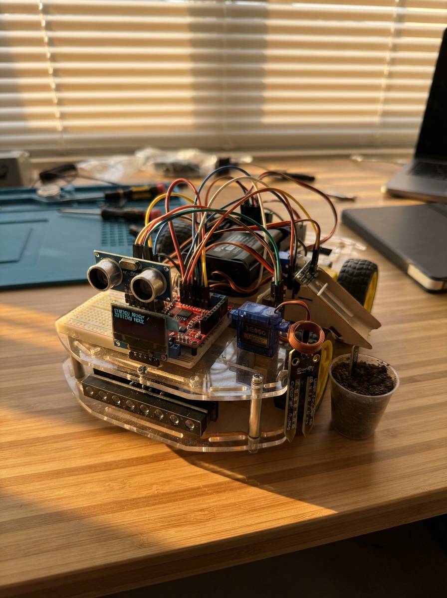
This autonomous waste-sorting robot uses line-following and object detection to autonomously navigate an arena and sort waste into three bins based on material type. The robot combines an ESP32 microcontroller with infrared line tracking, ultrasonic distance sensing, capacitive moisture detection, and inductive metal sensing to identify and route different waste materials to the correct disposal bin via servo-controlled gates.
This guide provides a complete wiring diagram, detailed parts list, assembly steps for the rolling frame and sensor array, and fully commented firmware. Builders will learn how to integrate multiple sensor types, coordinate servo control through a PWM driver, and implement state-machine logic for autonomous sorting behavior. The project is designed for robotics competitions and educational maker spaces.
Wiring diagram

Gather all the parts
Assemble it in 7 steps
1. Build the lower rolling frame
Bolt left_motor_1 and right_motor_1 to the lower plate with the wheels pointing straight ahead. Mount motor_driver_1 close to the motors. Connect left_motor_1 M+ to motor_driver_1 AOUT1 and M- to AOUT2 (left-wheel power); connect right_motor_1 M+ to BOUT1 and M- to BOUT2 (right-wheel power).
- Twist each pair of motor wires together and keep them short; this helps stop motor noise reaching the sensors.
- Never connect a motor wire to an ESP32 pin — motor power can damage the board.
2. Make the 5 V power rail
With battery_3s_1 disconnected, adjust buck_5v_1 with a multimeter until VOUT to GND measures exactly 5.0 V. Connect BAT+ to buck_5v_1 VIN and BAT- to buck_5v_1 GND (battery power). Connect VOUT to the 5 V rail and GND to the shared ground rail (regulated power). Feed the 5 V rail to the ESP32 VIN pin, motor_driver_1 VM, pca9685_1 V+, and the red VCC wire of every servo; connect all black or brown servo wires to the shared ground rail.
- Use a screw-terminal power splitter and thicker wire for the battery, converter, motors, and servo power wires.
- Set the converter to exactly 5.0 V before connecting the ESP32 — excessive voltage can permanently damage it.
- Every part must share the same ground rail or its signal wire will not work reliably.
3. Wire the ESP32, motors, and distance sensor
Mount the ESP32 in the middle tier. Connect motor_driver_1 AIN1 to GPIO16, AIN2 to GPIO17, BIN1 to GPIO18, and BIN2 to GPIO19 (motor-control signals). Connect motor_driver_1 nSLEEP to 3V3 (keeps the motor driver awake). Connect ultrasonic_1 TRIG to GPIO25 and ECHO to GPIO26 (distance signals). Connect moisture_sensor_1 AOUT to GPIO34 (moisture-reading signal). Connect the sonar and moisture sensor VCC pins to 3V3 and their GND pins to GND.
- Mount the ultrasonic sensor with its two round faces pointing forward and clear of the acrylic.
- Use the 3.3 V HC-SR04P in this design; a regular 5 V HC-SR04 can send an unsafe 5 V signal into the ESP32.
4. Connect the screen and servo controller
Connect oled_1 VCC to ESP32 3V3 (screen power), GND to GND (screen ground), SDA to GPIO21 (screen data), and SCL to GPIO22 (screen clock). On pca9685_1, connect VCC to ESP32 3V3 (safe signal-level power), GND to GND (ground), SDA to GPIO21 (shared data), SCL to GPIO22 (shared clock), and V+ to the separate 5 V rail (servo power). Mount the screen where its text is easy to read.
- The OLED and PCA9685 use the same SDA and SCL wires; join each matching pair together rather than choosing separate GPIO pins.
- Keep pca9685_1 VCC on 3.3 V and V+ on 5 V — connecting 5 V to VCC can send unsafe voltage into ESP32 data pins.
- Make sure VCC and GND are not swapped — swapped power can damage the screen or controller.
5. Fit the floor and waste sensors
Fix line_tracker_1 under the front of the robot, with its five sensors facing down about 3 to 5 mm above the mat. Connect VCC to 3V3 (power), GND to GND (ground), S1 to GPIO4, S2 to GPIO13, S3 to GPIO14, S4 to GPIO27, and S5 to GPIO33 (line signals, left to right). Mount metal_sensor_1 beside the chute and connect VCC to 3V3 (power), GND to GND (ground), and OUT to GPIO32 (metal signal). Put the sensing end of moisture_sensor_1 where waste touches it without wetting its electronics board.
- Use black tape under the line tracker while adjusting its tiny sensitivity controls.
- Do not let wet material touch the ESP32, motor driver, or buck converter — it can create a short circuit.
6. Connect the three bin servos through the PCA9685
Plug the wet_servo_1 three-wire connector into pca9685_1 PWM0, dry_servo_1 into PWM1, and metal_servo_1 into PWM2. On each servo plug, brown or black goes to GND (ground), red goes to V+ (5 V power), and orange or yellow goes to the PWM signal row (control). Fasten each servo horn only after its bin is in the closed, level position.
- Most PCA9685 boards label the three rows GND, V+, and signal. Follow those printed labels instead of relying only on the connector direction.
- A jammed servo can overheat its wires or make the ESP32 restart; switch off power if a servo buzzes continuously.
- Do not power the servo row from the ESP32 3V3 pin — it cannot supply enough current.
7. Test safely on the arena mat
Lift the wheels off the table for the first test. Confirm oled_1 shows text, place black tape under line_tracker_1, then bring an object in front of ultrasonic_1. Test each bin with a small dry item before using damp material. Finally place the robot on the track and confirm it turns toward the black line.
- If the robot turns away from the line, reverse the matching motor’s two wires at motor_driver_1, or change the line-sensor logic noted in the firmware.
- Keep fingers, loose clothing, and test items away from the wheels and bin linkages while the battery is connected.
Review all connections
1. Connections between "battery_3s_1" and "ESP32"
2. Connections between "buck_5v_1" and "ESP32"
3. Connections between "line_tracker_1" and "ESP32"
4. Connections between "ultrasonic_1" and "ESP32"
5. Connections between "oled_1" and "ESP32"
6. Connections between "wet_servo_1" and "ESP32"
7. Connections between "dry_servo_1" and "ESP32"
8. Connections between "metal_servo_1" and "ESP32"
9. Connections between "motor_driver_1" and "ESP32"
10. Connections between "left_motor_1" and "ESP32"
11. Connections between "right_motor_1" and "ESP32"
12. Connections between "moisture_sensor_1" and "ESP32"
13. Connections between "metal_sensor_1" and "ESP32"
14. Connections between "pca9685_1" and "ESP32"
Deploy the firmware
#include <Arduino.h>
#include <Wire.h>
#include <Adafruit_GFX.h>
#include <Adafruit_SSD1306.h>
#include <Adafruit_PWMServoDriver.h>

enum RobotState { FOLLOWING, STOPPED, SORTING };


// Forward declarations
void setMotors(int leftForward, int leftReverse, int rightForward, int rightReverse);
void stopMotors();
void driveForward();
void turnLeft();
void turnRight();
float readDistanceCm();
void drawStatus(float distanceCm, int moisture, bool metalDetected);
void tipBin(uint8_t channel, const char *label);
void followLine();

constexpr int SONAR_TRIG_PIN = 25;
constexpr int SONAR_ECHO_PIN = 26;
constexpr int LEFT_IN1_PIN = 16;
constexpr int LEFT_IN2_PIN = 17;
constexpr int RIGHT_IN1_PIN = 18;
constexpr int RIGHT_IN2_PIN = 19;
constexpr int MOISTURE_PIN = 34;
constexpr int LINE_S1_PIN = 4;
constexpr int LINE_S2_PIN = 13;
constexpr int LINE_S3_PIN = 14;
constexpr int LINE_S4_PIN = 27;
constexpr int LINE_S5_PIN = 33;
constexpr int METAL_SENSOR_PIN = 32;
constexpr int I2C_SDA_PIN = 21;
constexpr int I2C_SCL_PIN = 22;

constexpr uint8_t SCREEN_WIDTH = 128;
constexpr uint8_t SCREEN_HEIGHT = 64;
constexpr uint8_t OLED_ADDRESS = 0x3C;
constexpr uint8_t PCA9685_ADDRESS = 0x40;
constexpr uint8_t WET_SERVO_CHANNEL = 0;
constexpr uint8_t DRY_SERVO_CHANNEL = 1;
constexpr uint8_t METAL_SERVO_CHANNEL = 2;
constexpr uint16_t SERVO_CLOSED_PULSE = 180;
constexpr uint16_t SERVO_TIP_PULSE = 430;
constexpr int MOTOR_SPEED = 185;
constexpr int TURN_SPEED = 160;
constexpr float STOP_DISTANCE_CM = 10.0f;
constexpr int WET_THRESHOLD = 2100;
constexpr unsigned long STATUS_PERIOD_MS = 250;
constexpr unsigned long SORT_COOLDOWN_MS = 3000;

Adafruit_SSD1306 display(SCREEN_WIDTH, SCREEN_HEIGHT, &Wire, -1);
Adafruit_PWMServoDriver servoDriver(PCA9685_ADDRESS);
RobotState robotState = FOLLOWING;
String statusLine = "Starting";
unsigned long lastStatusUpdate = 0;
unsigned long lastSortTime = 0;

void setMotors(int leftForward, int leftReverse, int rightForward, int rightReverse) {
  ledcWrite(0, leftForward);
  ledcWrite(1, leftReverse);
  ledcWrite(2, rightForward);
  ledcWrite(3, rightReverse);
}

void stopMotors() { setMotors(0, 0, 0, 0); }
void driveForward() { setMotors(MOTOR_SPEED, 0, MOTOR_SPEED, 0); }
void turnLeft() { setMotors(0, TURN_SPEED, TURN_SPEED, 0); }
void turnRight() { setMotors(TURN_SPEED, 0, 0, TURN_SPEED); }

float readDistanceCm() {
  digitalWrite(SONAR_TRIG_PIN, LOW);
  delayMicroseconds(3);
  digitalWrite(SONAR_TRIG_PIN, HIGH);
  delayMicroseconds(10);
  digitalWrite(SONAR_TRIG_PIN, LOW);
  unsigned long pulse = pulseIn(SONAR_ECHO_PIN, HIGH, 25000);
  return pulse == 0 ? 999.0f : pulse * 0.0343f / 2.0f;
}

void drawStatus(float distanceCm, int moisture, bool metalDetected) {
  if (millis() - lastStatusUpdate < STATUS_PERIOD_MS) return;
  lastStatusUpdate = millis();
  display.clearDisplay();
  display.setTextColor(SSD1306_WHITE);
  display.setTextSize(1);
  display.setCursor(0, 0);
  display.println("Swachh-Bot 360");
  display.print("Mode: "); display.println(statusLine);
  display.print("Range: ");
  if (distanceCm >= 999.0f) display.println("--");
  else { display.print(distanceCm, 0); display.println(" cm"); }
  display.print("Moisture: "); display.println(moisture);
  display.print("Metal: "); display.println(metalDetected ? "YES" : "NO");
  display.display();
}

void tipBin(uint8_t channel, const char *label) {
  robotState = SORTING;
  statusLine = label;
  stopMotors();
  servoDriver.setPWM(channel, 0, SERVO_TIP_PULSE);
  delay(1100);
  servoDriver.setPWM(channel, 0, SERVO_CLOSED_PULSE);
  delay(500);
  lastSortTime = millis();
  statusLine = "Following line";
  robotState = FOLLOWING;
}

void followLine() {
  // Most line modules output LOW on black. Remove ! if your module outputs HIGH on black.
  bool leftOuter = !digitalRead(LINE_S1_PIN);
  bool leftInner = !digitalRead(LINE_S2_PIN);
  bool centre = !digitalRead(LINE_S3_PIN);
  bool rightInner = !digitalRead(LINE_S4_PIN);
  bool rightOuter = !digitalRead(LINE_S5_PIN);
  if (centre || (leftInner && rightInner)) driveForward();
  else if (leftOuter || leftInner) turnLeft();
  else if (rightOuter || rightInner) turnRight();
  else { stopMotors(); statusLine = "Line lost"; }
}

void setup() {
  Serial.begin(115200);
  Wire.begin(I2C_SDA_PIN, I2C_SCL_PIN);
  pinMode(SONAR_TRIG_PIN, OUTPUT);
  pinMode(SONAR_ECHO_PIN, INPUT);
  pinMode(LINE_S1_PIN, INPUT);
  pinMode(LINE_S2_PIN, INPUT);
  pinMode(LINE_S3_PIN, INPUT);
  pinMode(LINE_S4_PIN, INPUT);
  pinMode(LINE_S5_PIN, INPUT);
  pinMode(METAL_SENSOR_PIN, INPUT);

  ledcAttachChannel(LEFT_IN1_PIN, 20000, 8, 0);
  ledcAttachChannel(LEFT_IN2_PIN, 20000, 8, 1);
  ledcAttachChannel(RIGHT_IN1_PIN, 20000, 8, 2);
  ledcAttachChannel(RIGHT_IN2_PIN, 20000, 8, 3);
  stopMotors();

  servoDriver.begin();
  servoDriver.setOscillatorFrequency(27000000);
  servoDriver.setPWMFreq(50);
  servoDriver.setPWM(WET_SERVO_CHANNEL, 0, SERVO_CLOSED_PULSE);
  servoDriver.setPWM(DRY_SERVO_CHANNEL, 0, SERVO_CLOSED_PULSE);
  servoDriver.setPWM(METAL_SERVO_CHANNEL, 0, SERVO_CLOSED_PULSE);

  if (!display.begin(SSD1306_SWITCHCAPVCC, OLED_ADDRESS)) Serial.println("OLED not found");
  statusLine = "Following line";
}

void loop() {
  float distanceCm = readDistanceCm();
  int moisture = analogRead(MOISTURE_PIN);
  bool metalDetected = !digitalRead(METAL_SENSOR_PIN);

  if (robotState == FOLLOWING && distanceCm > STOP_DISTANCE_CM) {
    statusLine = "Following line";
    followLine();
  } else if (robotState == FOLLOWING) {
    stopMotors();
    statusLine = "Object detected";
    robotState = STOPPED;
  }

  if (robotState == STOPPED && millis() - lastSortTime > SORT_COOLDOWN_MS) {
    if (metalDetected) tipBin(METAL_SERVO_CHANNEL, "METAL CANS");
    else if (moisture > WET_THRESHOLD) tipBin(WET_SERVO_CHANNEL, "WET ORGANIC");
    else tipBin(DRY_SERVO_CHANNEL, "DRY RECYCLABLE");
  }

  drawStatus(distanceCm, moisture, metalDetected);
  delay(15);
}
Remix this project
Make it yours in one click
Open a full copy of this project in your own Schematik workspace — diagram, code, parts, and assembly steps included. Swap the sensor, add features, or redesign the whole thing with AI. The author's original stays untouched.
Related projects

Create A Complete Electrical Schematic Esp32 Sma
ESP32 · September 17, 2026Ayansh Agrawal
ESP32 Kare Ekran Projeleri
ESP32 · September 16, 2026Seref Ai
Component Qty --------------------------- ------
ESP32 · September 16, 2026Yathartha Chakrawal