Community project
Bicycle Motion Data Logger
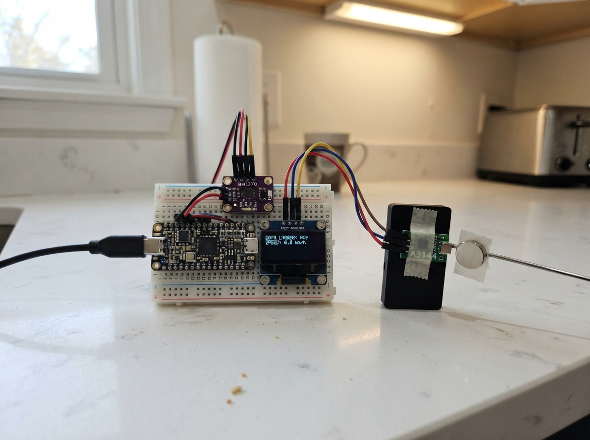
This project builds a compact motion data logger that captures acceleration, gyroscope, and wheel speed data from a bicycle in real time. The ESP32 reads a Bosch BMI270 inertial measurement unit for 3-axis motion, detects wheel rotations via a Hall-effect sensor and magnet, and displays live metrics on an SSD1306 OLED screen while logging all measurements to CSV format.
The guide provides a complete wiring diagram, parts list, and step-by-step assembly instructions for mounting the logger on a bicycle frame. Firmware is included with configurable sample rates and wheel circumference, making it easy to adapt the logger to different bike sizes and data collection needs.
Wiring diagram

Gather all the parts
Assemble it in 5 steps
1. Keep the board unpowered while wiring
Place the ESP32-S3 board, BMI270 breakout, OLED, and hall sensor module where you can reach their printed pin labels. Leave the USB cable unplugged until every wire has been checked.
- Use short jumper wires for the IMU and OLED so vibration is less likely to loosen them.
- Do not connect wires while USB power is plugged in — a misplaced wire can damage a sensor or the board.
2. Wire the motion sensor and screen
Connect BMI270 VCC to ESP32-S3 3V3 (power), BMI270 GND to GND (ground), BMI270 SDA to GPIO8 (data), and BMI270 SCL to GPIO9 (clock). Connect OLED VCC to ESP32-S3 3V3 (power), OLED GND to GND (ground), OLED SDA to GPIO8 (data), and OLED SCL to GPIO9 (clock). Also connect the BMI270 SDO pin to GND if the breakout exposes it; this selects the address used by the logger.
- Both small boards share GPIO8 and GPIO9; that is normal because they take turns using the same two data wires.
- Make sure VCC and GND are not swapped — swapped power can damage the BMI270 or OLED.
3. Wire the wheel rotation sensor
Connect the 3.3 V hall sensor module VCC to ESP32-S3 3V3 (power), GND to GND (ground), and OUT to GPIO4 (wheel-pulse signal). Keep this sensor powered only from 3.3 V, not 5 V, so its output remains safe for the ESP32-S3.
- Run the sensor cable along the frame and secure it with cable ties, leaving enough slack at the fork for steering.
- Keep the cable away from the brake disc, spokes, chain, and tyre — moving parts can cut the wire or pull the sensor loose.
4. Mount and align the magnet
Secure the magnet to one wheel spoke and fix the hall sensor to the fork or frame so the magnet passes the marked sensing face once per wheel rotation. Start with a 3 to 8 mm gap and turn the wheel by hand while checking that the rotation number changes on the OLED.
- Use thread-locking adhesive or a strong spoke mount; one magnet pass is counted as one rotation.
- A loose magnet can fly off into the wheel. Keep it firmly attached and clear of the brake rotor and spokes.
5. Secure the logger for data collection
Mount the ESP32-S3, OLED, and BMI270 in a small weather-protected enclosure on the bicycle frame. Keep the IMU firmly fixed in one orientation because its X, Y, and Z readings follow how the board is mounted. Plug the ESP32-S3 into USB after the wiring is complete.
- Before collecting research data, measure one full tyre rollout on the ground and replace WHEEL_CIRCUMFERENCE_M in the top of src/main.cpp with that distance in metres.
- Do not operate the bicycle with loose electronics or wires that can interfere with steering, brakes, pedals, or wheels.
Review all connections
1. Connections between "bmi270_1" and "ESP32"
2. Connections between "oled_1" and "ESP32"
3. Connections between "hall_1" and "ESP32"
Deploy the firmware
#include <Arduino.h>
#include <Wire.h>
#include "ImuDriver.h"
#include "HallSpeed.h"
#include "StatusDisplay.h"
#include "CsvLogger.h"

// Easy-to-change hardware and collection settings.
constexpr int I2C_SDA_PIN = 8;
constexpr int I2C_SCL_PIN = 9;
constexpr int HALL_PIN = 4;
constexpr uint8_t BMI270_ADDRESS = 0x68;
constexpr uint8_t OLED_ADDRESS = 0x3C;
constexpr uint32_t SAMPLE_RATE_HZ = 100;
constexpr uint32_t SAMPLE_INTERVAL_US = 1000000UL / SAMPLE_RATE_HZ;
constexpr float WHEEL_CIRCUMFERENCE_M = 2.105f;

ImuDriver imu;
HallSpeed wheel;
StatusDisplay display;
CsvLogger logger;
uint32_t nextSampleUs = 0;
uint32_t lastDisplayMs = 0;
ImuSample latestSample{};
float latestSpeedKph = 0.0f;

[[noreturn]] void haltWithMessage(const char *message) {
  Serial.println(message);
  while (true) delay(1000);
}

void setup() {
  logger.begin(115200);
  Wire.begin(I2C_SDA_PIN, I2C_SCL_PIN);
  Wire.setClock(400000);
  if (!imu.begin(Wire, BMI270_ADDRESS)) haltWithMessage("ERROR: BMI270 not found");
  if (!display.begin(Wire, OLED_ADDRESS)) haltWithMessage("ERROR: SSD1306 not found");
  wheel.begin(HALL_PIN, WHEEL_CIRCUMFERENCE_M);
  nextSampleUs = micros();
  Serial.println("# logger_ready");
}

void loop() {
  const uint32_t nowUs = micros();
  if ((int32_t)(nowUs - nextSampleUs) < 0) return;
  nextSampleUs += SAMPLE_INTERVAL_US;
  if ((int32_t)(nowUs - nextSampleUs) >= 0) nextSampleUs = nowUs + SAMPLE_INTERVAL_US;

  ImuSample sample;
  if (!imu.read(sample)) return;
  latestSample = sample;
  latestSpeedKph = wheel.speedKph();
  logger.log(millis(), sample, latestSpeedKph);

  if (millis() - lastDisplayMs >= 200) {
    lastDisplayMs = millis();
    display.showStatus(latestSample, latestSpeedKph, wheel.rotations());
  }
}
Remix this project
Make it yours in one click
Open a full copy of this project in your own Schematik workspace — diagram, code, parts, and assembly steps included. Swap the sensor, add features, or redesign the whole thing with AI. The author's original stays untouched.
Related projects

Create A Complete Electrical Schematic Esp32 Sma
ESP32 · September 17, 2026Ayansh Agrawal
ESP32 Kare Ekran Projeleri
ESP32 · September 16, 2026Seref Ai
Component Qty --------------------------- ------
ESP32 · September 16, 2026Yathartha Chakrawal