Community project
Blink Led Onboard Of Esp8266 Lolin
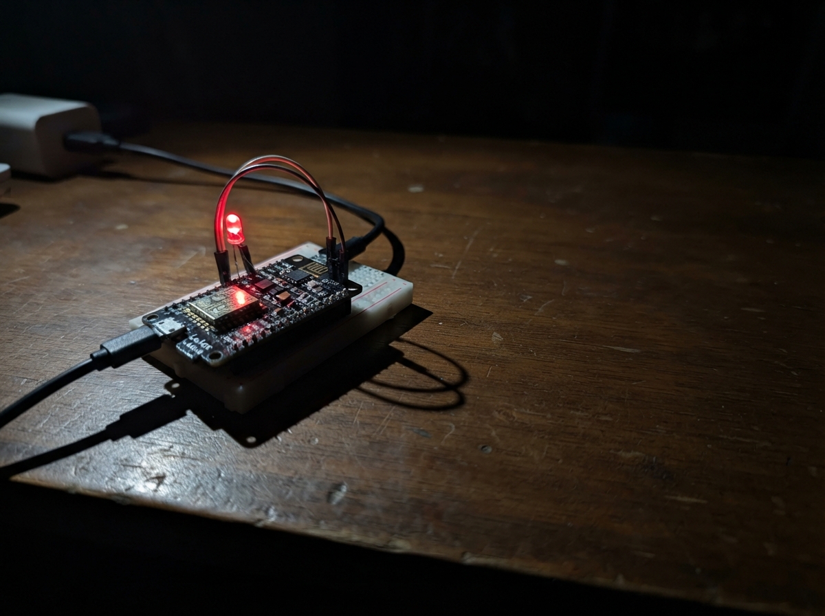
This project demonstrates the fundamentals of embedded programming by blinking the built-in LED on an ESP8266 LOLIN board. The onboard LED toggles on and off at a regular interval, providing immediate visual feedback that the microcontroller is running and responding to code.
The guide includes a complete parts list (just the LOLIN board and USB cable), a wiring diagram showing the simple USB connection, and ready-to-upload firmware written in Arduino. Builders will learn how to configure GPIO pins, use timing functions to create non-blocking delays, and work with active-LOW logic—essential concepts for any microcontroller project.
Wiring diagram
Assemble it in 2 steps
1. Use the built-in light
No extra LED or wires are needed. The small blue LED already fitted to the LOLIN D1 mini is connected inside the board, so leave the board on a non-conductive surface while you test it.
- The built-in LED is normally marked near D4 or the board’s blue indicator light.
- Do not rest the powered board on loose metal parts or a metal table, because they can touch its pins and damage it.
2. Connect the board by USB
Plug a USB data cable into the LOLIN D1 mini and your computer. The USB cable powers the board and lets Schematik install the blink program.
- The LED should blink about once per second: half a second on, then half a second off.
- Use a USB data cable, not a charge-only cable, or the computer cannot communicate with the board.
Deploy the firmware
#include <Arduino.h>

// On the LOLIN D1 mini the built-in LED is active LOW.
constexpr uint8_t LED_PIN = 2;
constexpr unsigned long BLINK_INTERVAL_MS = 100;

bool ledOn = false;
unsigned long lastToggleMs = 0;

void setup() {
  pinMode(LED_PIN, OUTPUT);
  digitalWrite(LED_PIN, HIGH);  // LED off
}

void loop() {
  const unsigned long now = millis();
  if (now - lastToggleMs >= BLINK_INTERVAL_MS) {
    lastToggleMs = now;
    ledOn = !ledOn;
    digitalWrite(LED_PIN, ledOn ? LOW : HIGH);
  }
}
Remix this project
Make it yours in one click
Open a full copy of this project in your own Schematik workspace — diagram, code, parts, and assembly steps included. Swap the sensor, add features, or redesign the whole thing with AI. The author's original stays untouched.