Community project
Brake Telemetry Monitor
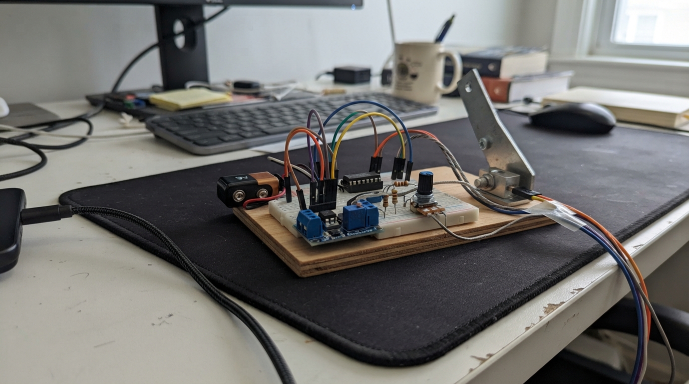
This brake telemetry monitor uses an ESP32 to track braking force, fluid level, and pad wear in real time. The load cell with instrumentation amplifier measures brake pressure, while a Hall-effect sensor and water level sensor monitor pad condition and fluid status. The system displays readings on a 16x2 LCD and triggers visual alerts when braking force exceeds safe thresholds or fluid drops below minimum levels.
The guide provides a complete wiring diagram, parts list, and step-by-step assembly instructions for integrating the 24V buck converter, logic-level shifter, and sensor conditioning circuits. Included firmware handles analog sampling, threshold detection, and display updates, giving makers a foundation for vehicle brake monitoring or test-stand applications.
Wiring diagram
Gather all the parts
Assemble it in 8 steps
1. Set the power converter first
With the 9 V battery disconnected, connect battery_9v + to lm2596_5v VIN+ and battery_9v - to VIN-. Use a multimeter to adjust the LM2596 output to exactly 5.0 V before connecting anything else. Connect VOUT+ to the 5V rail and VOUT- to the GND rail.
- Use a battery pack that can supply at least 1 A; a small rectangular PP3 9 V battery is not suitable for the motor and LED array.
- Do not connect the ESP32 until the buck output measures 5.0 V — a higher setting can damage the board and sensors.
2. Connect the ESP32 and low-voltage rails
Connect the 5V rail to the ESP32 VIN pin and the GND rail to an ESP32 GND pin. The ESP32 3V3 pin is the 3.3V rail for the Hall-sensor pull-up and the low-voltage side of the level converter.
- Do not put 5 V on an ESP32 GPIO pin; every ESP32 signal pin uses 3.3 V only.
3. Wire the load-cell measurement path
Connect load_cell_5kg Red/E+ to 5V and Black/E- to GND. Connect Green/S+ to ad620an pin 3 and White/S- to pin 2. Connect AD620 pin 7 to 5V, pins 4 and 5 to GND, and place c_ad620 directly between pins 7 and 4. Connect the gain control as AD620 pin 1 through gain_limit_1k to the gain_pot_5k wiper, then its CCW end to AD620 pin 8. Connect AD620 pin 6 through load_adc_top (20 kΩ) to GPIO34; connect load_adc_bottom (10 kΩ) from that GPIO34 junction to GND.
- Start with the gain knob turned to its lowest-gain end, then increase it only while watching the displayed force reading.
- The 20 kΩ and 10 kΩ parts are a required safety divider; removing them can put more than 3.3 V into GPIO34 and damage the ESP32.
4. Wire the fluid and pad-wear sensors
Connect water_sensor + to 5V and - to GND, with c_water across those same two power pins. Connect its S pin through level_adc_top (20 kΩ) to GPIO35, and connect level_adc_bottom (10 kΩ) from the GPIO35 junction to GND. Connect hall_a3144e pin 1 to 5V, pin 2 to GND, and pin 3 to GPIO4. Connect hall_pullup_10k from Hall pin 3 to 3V3, and place c_hall between Hall VCC and GND.
- Keep the 10 kΩ Hall pull-up connected to 3.3V, not 5V — otherwise the Hall output can damage GPIO4.
5. Wire the LCD through its translator board
Connect i2c_level_shifter HV to 5V, LV to 3V3, and GND to GND. Connect ESP32 GPIO21 to LV1 and GPIO22 to LV2. Connect HV1 to lcd_1602 SDA and HV2 to lcd_1602 SCL. Connect LCD VCC to 5V, LCD GND to GND, and place c_lcd across LCD VCC and GND.
- If the LCD backlight works but no letters appear, turn the small contrast screw on its backpack slowly.
- Make sure VCC and GND are not swapped — swapped power can damage the LCD backpack.
6. Build the ten-light brake warning array
For each branch, connect the 5V rail to one led_r1 through led_r10 220 Ω resistor, then to that matching led_1 through led_10 long LED leg. Join all short LED legs to driver_2n2222 collector. Connect its emitter to GND. Connect GPIO16 through base_resistor_1k to the transistor base.
- Every LED needs its own 220 Ω resistor — sharing one resistor can overheat an LED and makes brightness uneven.
- Check the 2N2222 lead order from its specific datasheet; TO-92 lead order differs between manufacturers.
7. Build the independent motor circuit
Connect the 5V rail to limit_switch COM, its NO terminal to motor_5v +, and motor_5v - to GND. Put motor_diode_1n4007 directly across the motor: its striped cathode end goes to motor + and its unstriped anode end goes to motor -.
- The striped diode end must go to the motor's 5V side — reversing it creates a short circuit when the switch closes.
- The motor is independent of the ESP32: it runs whenever the limit switch closes.
8. Perform the first safe power-up
Inspect every 5V and GND connection, then connect the 9 V battery pack. Confirm the LCD starts, keep hands clear of the motor, and only then connect the ESP32 USB cable for programming.
- Do not simultaneously feed the ESP32 VIN from the LM2596 and from USB unless your particular DevKit board explicitly supports this; disconnect the battery supply while programming over USB.
Review all connections
1. Connections between "battery_9v" and "ESP32"
2. Connections between "lm2596_5v" and "ESP32"
3. Connections between "load_cell_5kg" and "ESP32"
4. Connections between "ad620an" and "ESP32"
5. Connections between "load_adc_bottom" and "ESP32"
6. Connections between "water_sensor" and "ESP32"
7. Connections between "level_adc_bottom" and "ESP32"
8. Connections between "hall_a3144e" and "ESP32"
9. Connections between "hall_pullup_10k" and "ESP32"
10. Connections between "lcd_1602" and "ESP32"
11. Connections between "i2c_level_shifter" and "ESP32"
12. Connections between "base_resistor_1k" and "ESP32"
13. Connections between "driver_2n2222" and "ESP32"
14. Connections between "limit_switch" and "ESP32"
15. Connections between "motor_5v" and "ESP32"
16. Connections between "motor_diode_1n4007" and "ESP32"
17. Connections between "c_ad620" and "ESP32"
18. Connections between "c_hall" and "ESP32"
19. Connections between "c_water" and "ESP32"
20. Connections between "c_lcd" and "ESP32"
21. Connections between "led_r1" and "ESP32"
22. Connections between "led_1" and "ESP32"
23. Connections between "led_r2" and "ESP32"
24. Connections between "led_2" and "ESP32"
25. Connections between "led_r3" and "ESP32"
26. Connections between "led_3" and "ESP32"
27. Connections between "led_r4" and "ESP32"
28. Connections between "led_4" and "ESP32"
29. Connections between "led_r5" and "ESP32"
30. Connections between "led_5" and "ESP32"
31. Connections between "led_r6" and "ESP32"
32. Connections between "led_6" and "ESP32"
33. Connections between "led_r7" and "ESP32"
34. Connections between "led_7" and "ESP32"
35. Connections between "led_r8" and "ESP32"
36. Connections between "led_8" and "ESP32"
37. Connections between "led_r9" and "ESP32"
38. Connections between "led_9" and "ESP32"
39. Connections between "led_r10" and "ESP32"
40. Connections between "led_10" and "ESP32"
41. Connections between "load_adc_top" and "ESP32"
42. Connections between "level_adc_top" and "ESP32"
43. Connections between "gain_limit_1k" and "ESP32"
Deploy the firmware
#include <Arduino.h>
#include <Wire.h>
#include <LiquidCrystal_I2C.h>

constexpr int LOAD_ADC_PIN = 34;
constexpr int LEVEL_ADC_PIN = 35;
constexpr int HALL_PIN = 4;
constexpr int BRAKE_LED_PIN = 16;
constexpr int I2C_SDA_PIN = 21;
constexpr int I2C_SCL_PIN = 22;
constexpr uint8_t LCD_ADDRESS = 0x27;
constexpr uint32_t SAMPLE_INTERVAL_MS = 250;
constexpr int BRAKE_FORCE_ALERT_RAW = 1800;
constexpr int LOW_FLUID_PERCENT = 25;

LiquidCrystal_I2C lcd(LCD_ADDRESS, 16, 2);
uint32_t lastSampleMs = 0;
char previousLine1[17] = "";
char previousLine2[17] = "";

int readAverage(int pin) {
  constexpr int samples = 8;
  uint32_t total = 0;
  for (int i = 0; i < samples; ++i) {
    total += analogRead(pin);
  }
  return total / samples;
}

void updateDisplay(const char *line1, const char *line2) {
  if (strcmp(line1, previousLine1) != 0) {
    lcd.setCursor(0, 0);
    lcd.print("                ");
    lcd.setCursor(0, 0);
    lcd.print(line1);
    strncpy(previousLine1, line1, 16);
    previousLine1[16] = '\0';
  }
  if (strcmp(line2, previousLine2) != 0) {
    lcd.setCursor(0, 1);
    lcd.print("                ");
    lcd.setCursor(0, 1);
    lcd.print(line2);
    strncpy(previousLine2, line2, 16);
    previousLine2[16] = '\0';
  }
}

void setup() {
  Serial.begin(115200);
  pinMode(HALL_PIN, INPUT);
  pinMode(BRAKE_LED_PIN, OUTPUT);
  digitalWrite(BRAKE_LED_PIN, LOW);

  analogReadResolution(12);
  analogSetPinAttenuation(LOAD_ADC_PIN, ADC_11db);
  analogSetPinAttenuation(LEVEL_ADC_PIN, ADC_11db);

  Wire.begin(I2C_SDA_PIN, I2C_SCL_PIN);
  lcd.init();
  lcd.backlight();
  updateDisplay("Brake telemetry", "Starting...");
}

void loop() {
  const uint32_t now = millis();
  if (now - lastSampleMs < SAMPLE_INTERVAL_MS) {
    return;
  }
  lastSampleMs = now;

  const int forceRaw = readAverage(LOAD_ADC_PIN);
  const int levelRaw = readAverage(LEVEL_ADC_PIN);
  const int fluidPercent = constrain(map(levelRaw, 0, 4095, 0, 100), 0, 100);
  const bool padWearAlert = digitalRead(HALL_PIN) == LOW;
  const bool forceAlert = forceRaw >= BRAKE_FORCE_ALERT_RAW;
  const bool fluidAlert = fluidPercent <= LOW_FLUID_PERCENT;
  const bool brakeAlert = forceAlert || fluidAlert || padWearAlert;

  digitalWrite(BRAKE_LED_PIN, brakeAlert ? HIGH : LOW);

  char line1[17];
  char line2[17];
  snprintf(line1, sizeof(line1), "Force:%4d %s", forceRaw, forceAlert ? "!" : " ");
  if (fluidAlert) {
    snprintf(line2, sizeof(line2), "FLUID LOW %3d%%", fluidPercent);
  } else if (padWearAlert) {
    snprintf(line2, sizeof(line2), "PAD WEAR ALERT ");
  } else {
    snprintf(line2, sizeof(line2), "Fluid:%3d%% OK", fluidPercent);
  }
  updateDisplay(line1, line2);

  Serial.printf("force_raw=%d, fluid=%d%%, pad_wear=%s, alert=%s\n",
                forceRaw, fluidPercent, padWearAlert ? "YES" : "NO",
                brakeAlert ? "YES" : "NO");
}
Remix this project
Make it yours in one click
Open a full copy of this project in your own Schematik workspace — diagram, code, parts, and assembly steps included. Swap the sensor, add features, or redesign the whole thing with AI. The author's original stays untouched.