Community project
PlayStation-Controlled Blinking Rover
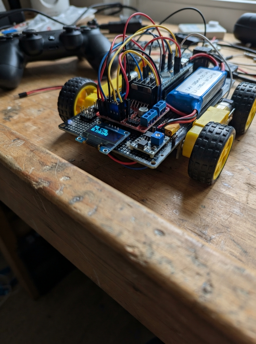
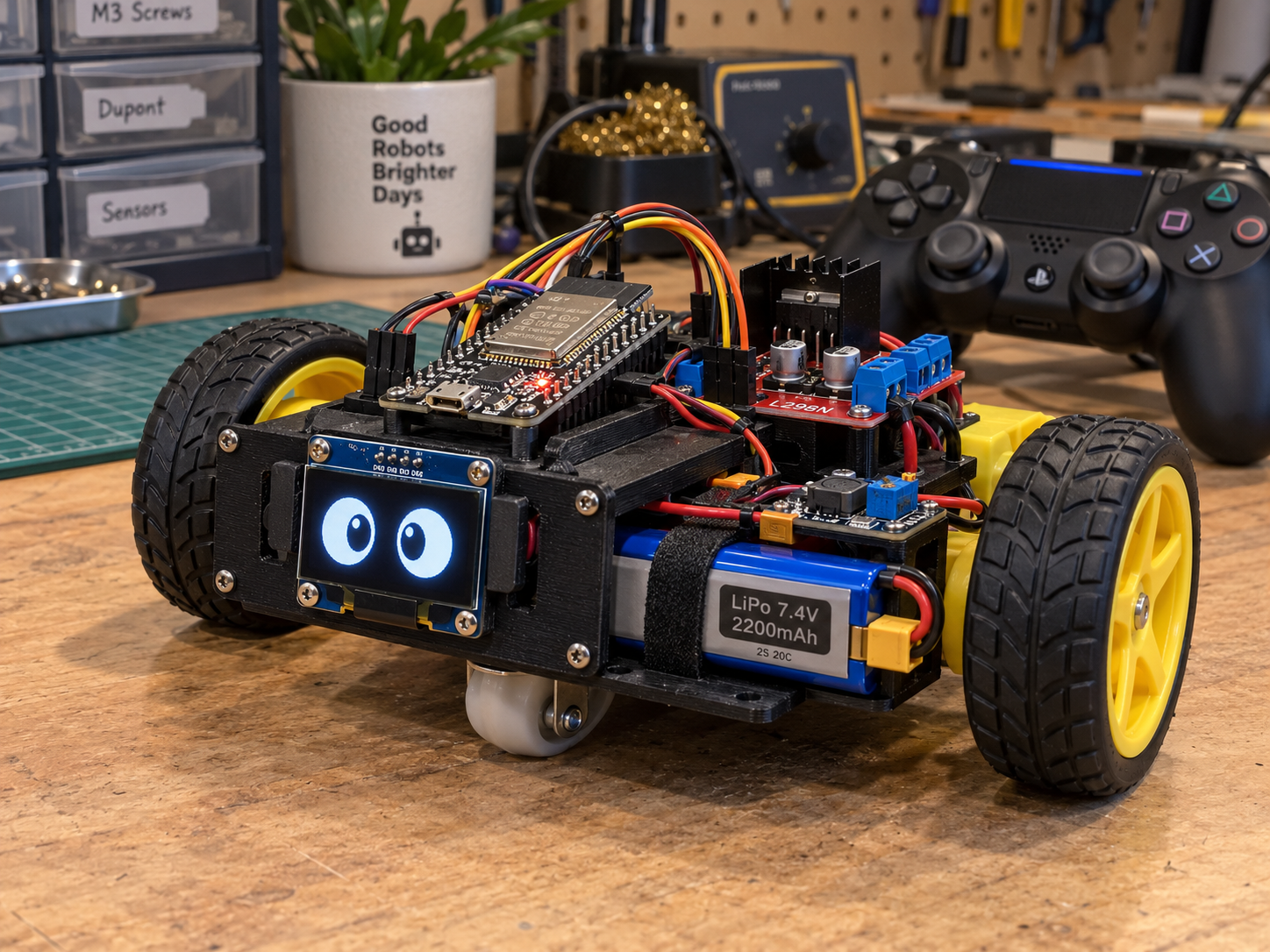
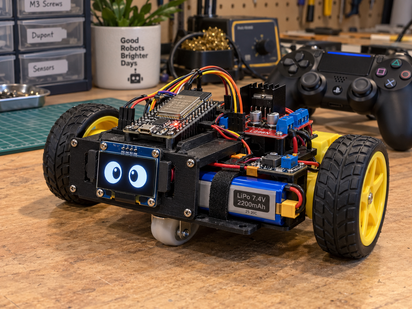
Build a small wheeled rover controlled wirelessly via PlayStation 4 controller, complete with an expressive OLED "eye" display that blinks autonomously. The rover uses dual TT motors with a 1:90 gear ratio for precise movement, powered by a 7.4V LiPo battery and managed through an L298N motor driver controlled by an ESP32 microcontroller.
This guide provides a complete wiring diagram, parts list, and step-by-step assembly instructions to get the rover moving and blinking. The included firmware handles PS4 controller input with joystick dead zones, motor direction control via PWM, and autonomous blinking animations on the SSD1306 OLED display—everything needed to bring this expressive little robot to life.
Wiring diagram

Gather all the parts
Assemble it in 6 steps
1. Fit the wheels and motors
Push a wheel onto each motor shaft, then fasten left_motor and right_motor into the two-wheel rover chassis. Put the small free caster wheel at the other end so the rover can turn freely.
- Keep both motor wires facing toward the middle of the chassis so they cannot rub against the wheels.
- Do not let bare motor tabs touch each other or the metal chassis; that can short the battery.
2. Mount the controller and eye screen
Secure the ESP32 and motor_driver on the top plate with spacers or strong double-sided tape. Put eye_screen at the front, facing outward, so its eyes are visible. Keep the screen's metal pins from touching the motor driver.
- Leave the ESP32 USB socket reachable so you can plug it in later.
3. Connect the motors to the driver
Connect the two wires from left_motor to OUT1 and OUT2 on motor_driver. Connect the two wires from right_motor to OUT3 and OUT4. These are the wires that carry motor power.
- If a wheel later turns the wrong way, swap only that motor's two wires after disconnecting the battery.
- Never move motor wires while the battery is connected; a loose wire can cause a short circuit.
4. Connect the ESP32 control wires
Connect motor_driver IN1 to ESP32 GPIO13 (left direction), IN2 to GPIO14 (left direction), IN3 to GPIO27 (right direction), IN4 to GPIO32 (right direction), ENA to GPIO25 (left enable), and ENB to GPIO26 (right enable). Connect eye_screen SDA to GPIO21 (data) and SCL to GPIO22 (clock). Connect eye_screen VCC to 3V3 (power) and GND to GND (ground).
- Use a separate wire color for every control wire and write the GPIO number on a small piece of tape if needed.
- Make sure the screen's VCC and GND are not swapped — swapped power can damage the screen.
5. Set up the battery power wires
Before connecting it, adjust logic_buck with a meter until its VOUT+ and VOUT- measure 5 V. Connect battery BAT+ to motor_driver VS (motor power) and to logic_buck VIN+ (converter input). Connect battery BAT- to the shared GND (ground), including motor_driver GND and logic_buck VIN-. Connect logic_buck VOUT+ to the ESP32 VIN/5V pin and motor_driver 5V pin (power), then VOUT- to the shared GND (ground).
- All GND wires must join together; this gives the ESP32 and motor driver the same electrical reference.
- Do not connect the 7.4 V battery directly to the ESP32 3V3 pin or to the OLED; it can permanently damage them.
- Check the buck converter output with a meter before plugging it into the ESP32.
6. Power up safely
Lift the rover so its wheels are off the table, then connect the battery. The eyes should appear on eye_screen and blink occasionally. Keep the wheels raised for the first controller test.
- If the display stays blank, disconnect the battery first and recheck its 3V3, GND, SDA, and SCL wires.
- Keep fingers, hair, and loose wires away from the wheels when the battery is connected.
Review all connections
1. Connections between "battery" and "ESP32"
2. Connections between "logic_buck" and "ESP32"
3. Connections between "motor_driver" and "ESP32"
4. Connections between "eye_screen" and "ESP32"
Deploy the firmware
#include <Arduino.h>
#include <Wire.h>
#include <Adafruit_GFX.h>
#include <Adafruit_SSD1306.h>
#include <PS4Controller.h>

constexpr int LEFT_IN1 = 13;
constexpr int LEFT_IN2 = 14;
constexpr int RIGHT_IN1 = 27;
constexpr int RIGHT_IN2 = 32;
constexpr int LEFT_EN = 25;
constexpr int RIGHT_EN = 26;
constexpr int OLED_SDA = 21;
constexpr int OLED_SCL = 22;

constexpr uint8_t SCREEN_WIDTH = 128;
constexpr uint8_t SCREEN_HEIGHT = 64;
constexpr int JOYSTICK_DEAD_ZONE = 28;

Adafruit_SSD1306 display(SCREEN_WIDTH, SCREEN_HEIGHT, &Wire, -1);

bool eyesClosed = false;
unsigned long blinkStartedAt = 0;
unsigned long nextBlinkAt = 0;

void setMotorPins(int pinA, int pinB, int direction) {
  if (direction > 0) {
    digitalWrite(pinA, HIGH);
    digitalWrite(pinB, LOW);
  } else if (direction < 0) {
    digitalWrite(pinA, LOW);
    digitalWrite(pinB, HIGH);
  } else {
    digitalWrite(pinA, LOW);
    digitalWrite(pinB, LOW);
  }
}

void stopRover() {
  setMotorPins(LEFT_IN1, LEFT_IN2, 0);
  setMotorPins(RIGHT_IN1, RIGHT_IN2, 0);
}

void drawEyes(bool closed) {
  display.clearDisplay();
  if (closed) {
    display.drawLine(24, 32, 52, 32, SSD1306_WHITE);
    display.drawLine(76, 32, 104, 32, SSD1306_WHITE);
  } else {
    display.fillRoundRect(24, 17, 28, 32, 12, SSD1306_WHITE);
    display.fillRoundRect(76, 17, 28, 32, 12, SSD1306_WHITE);
    display.fillCircle(42, 33, 7, SSD1306_BLACK);
    display.fillCircle(94, 33, 7, SSD1306_BLACK);
  }
  display.display();
}

void updateBlink() {
  const unsigned long now = millis();
  if (!eyesClosed && now >= nextBlinkAt) {
    eyesClosed = true;
    blinkStartedAt = now;
    drawEyes(true);
  } else if (eyesClosed && now - blinkStartedAt >= 150) {
    eyesClosed = false;
    nextBlinkAt = now + random(2500, 6000);
    drawEyes(false);
  }
}

int applyDeadZone(int value) {
  return abs(value) < JOYSTICK_DEAD_ZONE ? 0 : value;
}

void driveFromController() {
  const int throttle = -applyDeadZone(PS4.LStickY());
  const int steer = applyDeadZone(PS4.LStickX());

  if (throttle == 0 && steer == 0) {
    stopRover();
    return;
  }

  int leftCommand = throttle + steer;
  int rightCommand = throttle - steer;
  leftCommand = constrain(leftCommand, -127, 127);
  rightCommand = constrain(rightCommand, -127, 127);

  setMotorPins(LEFT_IN1, LEFT_IN2, (leftCommand > 0) - (leftCommand < 0));
  setMotorPins(RIGHT_IN1, RIGHT_IN2, (rightCommand > 0) - (rightCommand < 0));
}

void setup() {
  Serial.begin(115200);
  randomSeed(esp_random());

  pinMode(LEFT_IN1, OUTPUT);
  pinMode(LEFT_IN2, OUTPUT);
  pinMode(RIGHT_IN1, OUTPUT);
  pinMode(RIGHT_IN2, OUTPUT);
  pinMode(LEFT_EN, OUTPUT);
  pinMode(RIGHT_EN, OUTPUT);
  digitalWrite(LEFT_EN, HIGH);
  digitalWrite(RIGHT_EN, HIGH);
  stopRover();

  Wire.begin(OLED_SDA, OLED_SCL);
  if (!display.begin(SSD1306_SWITCHCAPVCC, 0x3C)) {
    Serial.println("OLED was not found at address 0x3C.");
    while (true) {
      delay(1000);
    }
  }
  drawEyes(false);
  nextBlinkAt = millis() + random(2500, 6000);

  // The paired PlayStation controller provides the rover's left-stick commands.
  PS4.begin();
  Serial.println("Rover ready. Pair the PS4 controller, then use its left stick to drive.");
}

void loop() {
  updateBlink();

  if (PS4.isConnected()) {
    driveFromController();
  } else {
    stopRover();
  }

  delay(10);
}
Download project files
Remix this project
Make it yours in one click
Open a full copy of this project in your own Schematik workspace — diagram, code, parts, and assembly steps included. Swap the sensor, add features, or redesign the whole thing with AI. The author's original stays untouched.