Community project
Hydraulic Brake Telemetry Station
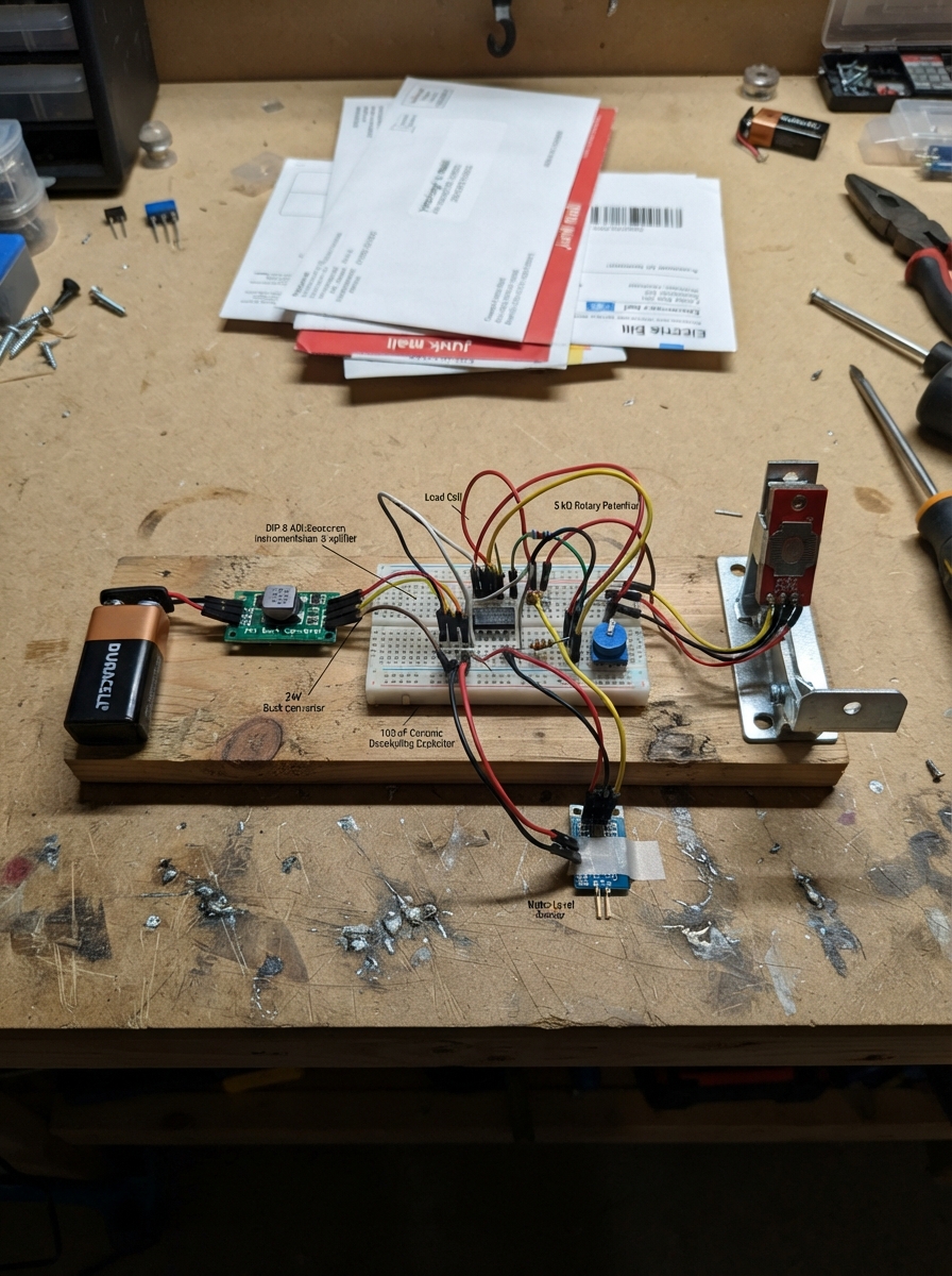
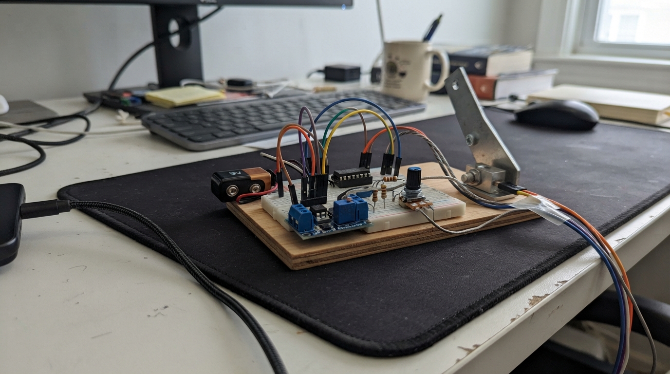
This hydraulic brake telemetry station monitors brake system health in real time using an ESP32 microcontroller. It measures brake force through a load cell and instrumentation amplifier, tracks hydraulic fluid level with a water level sensor, and detects brake pad wear using a Hall effect sensor. The system displays all readings on a 16x2 LCD screen, providing immediate feedback on brake performance and maintenance needs.
Builders will receive a complete wiring diagram showing power distribution from a 9V battery through a 24V buck converter, detailed schematics for the force and fluid sensing circuits with their respective voltage dividers, step-by-step assembly instructions, and ready-to-upload Arduino firmware. The guide includes a safe bench demonstrator setup for testing before integration into a vehicle system.
Wiring diagram

Gather all the parts
Assemble it in 8 steps
1. Set the 5 V supply before connecting electronics
Connect battery_9v positive to buck_5v VIN+ and battery negative to buck_5v VIN-. With only the battery and buck converter connected, turn the small LM2596 adjustment screw until a meter reads 5.00 V between VOUT+ and VOUT-. This creates the 5 V rail (power) and VOUT- is the common ground rail (ground).
- Measure the voltage again after each small adjustment; the screw is sensitive.
- Do not connect the ESP32, LCD, sensors, or motor until the buck converter measures 5.00 V — a higher setting can damage 5 V parts and the ESP32 VIN input.
2. Connect the ESP32 power rails
Connect buck_5v VOUT+ to the ESP32 VIN pin (power) and buck_5v VOUT- to an ESP32 GND pin (ground). Use the ESP32 3V3 pin only as the 3.3 V logic rail for the hall pull-up and level shifter; do not connect 5 V to 3V3.
- Never swap VIN and GND, and never put the 5 V rail on the ESP32 3V3 pin — either mistake can damage the board.
3. Wire the force sensor and protected force input
Connect load_cell_5kg red E+ to 5 V (power), black E- to GND (ground), green A+/S+ to ad620an Pin 3 +IN (signal), and white A-/S- to Pin 2 -IN (signal). Connect ad620an Pin 7 VS+ to 5 V (power), Pin 4 VS- and Pin 5 REF to GND (ground). Put ad620_decouple directly from Pin 7 to Pin 4 (noise filtering). Tie the gain_pot_5k wiper to End A; connect that pair to Pin 1 RG. Connect the other pot end through gain_limit_150r to Pin 8 RG. Connect Pin 6 OUT through force_divider_top 10 kΩ to the FORCE_ADC junction; connect that junction to force_divider_bottom 20 kΩ to GND and to ESP32 GPIO34 (signal).
- Keep the load-cell signal wires short and away from the motor wires. Turn the gain control to its highest-resistance end before applying force, then increase gain slowly while watching the LCD.
- The AD620 gain network can amplify a tiny load-cell signal strongly; do not turn the potentiometer to near-zero resistance, because that can make the amplifier saturate. The divider is required — GPIO34 must never see 5 V.
4. Wire the brake-fluid level input
Connect water_level + to 5 V (power) and - to GND (ground). Connect its S output through water_divider_top 10 kΩ to the FLUID_ADC junction. From that junction connect water_divider_bottom 20 kΩ to GND and a wire to ESP32 GPIO35 (signal).
- GPIO35 must receive the divided signal only — connecting the 5 V sensor output directly can damage the ESP32. Keep the exposed water-sensor traces away from actual brake fluid; use this hobby sensor only as a level demonstrator, not in a hydraulic brake reservoir.
5. Wire the pad-wear hall sensor
With the flat face of a typical TO-92 A3144E toward you and its leads pointing down, verify the package marking for your exact part before wiring. Connect Pin 1 VCC to 5 V (power), Pin 2 GND to GND (ground), and Pin 3 OUT to ESP32 GPIO4 (signal). Connect hall_pullup 10 kΩ between the same OUT/GPIO4 signal and ESP32 3V3 (signal pull-up).
- Bring the magnet close to the labeled face of the sensor and check that the LCD changes from WEAR! to PAD OK.
- Do not connect the pull-up resistor to 5 V — GPIO4 is a 3.3 V-only ESP32 input. Pin order varies among look-alike TO-92 sensors, so confirm the A3144E data sheet marking before soldering.
6. Wire the LCD through the level shifter
Connect level_shifter HV to 5 V (power), LV to ESP32 3V3 (power), and GND to the common ground rail (ground). Connect ESP32 GPIO21 to LV1 (data), HV1 to lcd1602 SDA (data), ESP32 GPIO22 to LV2 (data), and HV2 to lcd1602 SCL (data). Connect lcd1602 VCC to 5 V (power) and GND to GND (ground).
- Make sure VCC and GND are not swapped — swapped power can damage the LCD. The common PCF8574 LCD address is 0x27; if the screen stays blank but the backlight is on, your backpack may instead use 0x3F.
7. Build the independent pedal motor and brake-light wiring
Connect limit_switch COM to 5 V (power). Connect NC to motor_5v Motor + (power), and Motor - to GND (ground), so the motor runs when the pedal switch is released. Connect flyback_diode cathode, the end marked with a stripe, to Motor + and its anode to Motor - (protection). Connect NO only through base_resistor 1 kΩ to transistor_2n2222 BASE. Connect its EMITTER to GND and COLLECTOR to the joined LED cathodes. For each of the 10 brake LEDs, connect its anode through its own 220 Ω resistor to 5 V; join all cathodes at the transistor collector.
- The stripe on the 1N4007 must face the motor positive terminal — reversing it removes the motor-spike protection. Every LED needs its own 220 Ω resistor; do not share one resistor across all ten LEDs. Verify the actual motor's running and stall current is below the switch, 1N4007, battery, and LM2596 ratings.
8. Test the safe bench demonstrator
Keep this circuit off any vehicle brake system. First test the pedal switch with the motor shaft clear and the LEDs visible: released should run the motor with LEDs off; pressed should stop the motor with LEDs on. Then power the ESP32 and check the LCD readings and hall-sensor response.
- This is a low-voltage educational monitoring demonstrator, not a roadworthy or safety-certified hydraulic-brake controller. A rectangular 9 V PP3 battery is often too weak for a motor plus ten LEDs and may sag or heat; use a current-capable 9 V source for bench testing if it cannot hold the regulated 5 V rail.
Review all connections
1. Connections between "battery_9v" and "ESP32"
2. Connections between "buck_5v" and "ESP32"
3. Connections between "load_cell_5kg" and "ESP32"
4. Connections between "ad620an" and "ESP32"
5. Connections between "ad620_decouple" and "ESP32"
6. Connections between "gain_pot_5k" and "ESP32"
7. Connections between "gain_limit_150r" and "ESP32"
8. Connections between "force_divider_top" and "ESP32"
9. Connections between "force_divider_bottom" and "ESP32"
10. Connections between "water_level" and "ESP32"
11. Connections between "water_divider_top" and "ESP32"
12. Connections between "water_divider_bottom" and "ESP32"
13. Connections between "a3144e" and "ESP32"
14. Connections between "hall_pullup" and "ESP32"
15. Connections between "level_shifter" and "ESP32"
16. Connections between "lcd1602" and "ESP32"
17. Connections between "limit_switch" and "ESP32"
18. Connections between "motor_5v" and "ESP32"
19. Connections between "flyback_diode" and "ESP32"
20. Connections between "base_resistor" and "ESP32"
21. Connections between "transistor_2n2222" and "ESP32"
22. Connections between "led_resistors" and "ESP32"
Deploy the firmware
#include <Arduino.h>
#include <Wire.h>
#include <LiquidCrystal_I2C.h>

// Wiring labels: GPIO34 = FORCE_ADC, GPIO35 = FLUID_ADC,
// GPIO4 = PAD_WEAR_HALL, GPIO21 = I2C_SDA, GPIO22 = I2C_SCL.
constexpr uint8_t FORCE_ADC_PIN = 34;
constexpr uint8_t FLUID_ADC_PIN = 35;
constexpr uint8_t HALL_PIN = 4;
constexpr uint8_t I2C_SDA_PIN = 21;
constexpr uint8_t I2C_SCL_PIN = 22;
constexpr uint8_t LCD_ADDRESS = 0x27;
constexpr uint32_t SCREEN_INTERVAL_MS = 250;

LiquidCrystal_I2C lcd(LCD_ADDRESS, 16, 2);

uint16_t readAverage(uint8_t pin) {
  uint32_t total = 0;
  for (uint8_t i = 0; i < 16; ++i) total += analogRead(pin);
  return total / 16;
}

void showStatus(uint16_t forceRaw, uint16_t fluidRaw, bool magnetDetected) {
  const uint8_t forcePercent = constrain(map(forceRaw, 0, 4095, 0, 100), 0, 100);
  const uint8_t fluidPercent = constrain(map(fluidRaw, 0, 4095, 0, 100), 0, 100);
  lcd.setCursor(0, 0);
  lcd.printf("Force:%3u%%     ", forcePercent);
  lcd.setCursor(0, 1);
  lcd.printf("Fluid:%3u%% %s", fluidPercent, magnetDetected ? "PAD OK" : "WEAR!");
}

void setup() {
  Serial.begin(115200);
  pinMode(HALL_PIN, INPUT);  // The external 10 kΩ resistor pulls this line to 3.3 V.
  analogReadResolution(12);
  analogSetPinAttenuation(FORCE_ADC_PIN, ADC_11db);
  analogSetPinAttenuation(FLUID_ADC_PIN, ADC_11db);
  Wire.begin(I2C_SDA_PIN, I2C_SCL_PIN);
  lcd.init();
  lcd.backlight();
  lcd.setCursor(0, 0);
  lcd.print("Brake Monitor");
  lcd.setCursor(0, 1);
  lcd.print("Starting...     ");
  delay(1000);
  lcd.clear();
}

void loop() {
  static uint32_t lastScreenUpdate = 0;
  const uint32_t now = millis();
  if (now - lastScreenUpdate < SCREEN_INTERVAL_MS) return;
  lastScreenUpdate = now;
  const uint16_t forceRaw = readAverage(FORCE_ADC_PIN);
  const uint16_t fluidRaw = readAverage(FLUID_ADC_PIN);
  const bool magnetDetected = digitalRead(HALL_PIN) == LOW;
  showStatus(forceRaw, fluidRaw, magnetDetected);
  Serial.printf("force=%u fluid=%u pad=%s\n", forceRaw, fluidRaw,
                magnetDetected ? "OK" : "WEAR");
}
Remix this project
Make it yours in one click
Open a full copy of this project in your own Schematik workspace — diagram, code, parts, and assembly steps included. Swap the sensor, add features, or redesign the whole thing with AI. The author's original stays untouched.