Community project
Build A Comprehensive Football/soccer Video Anal
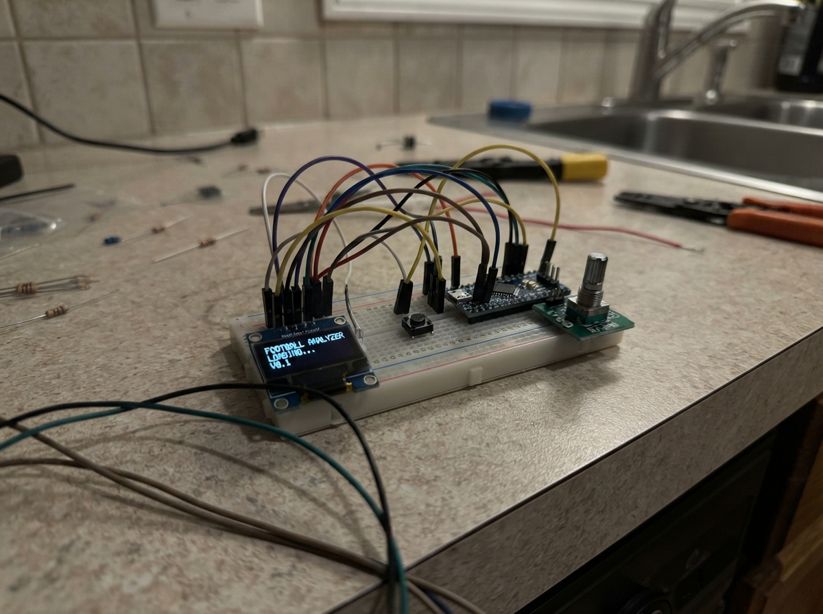
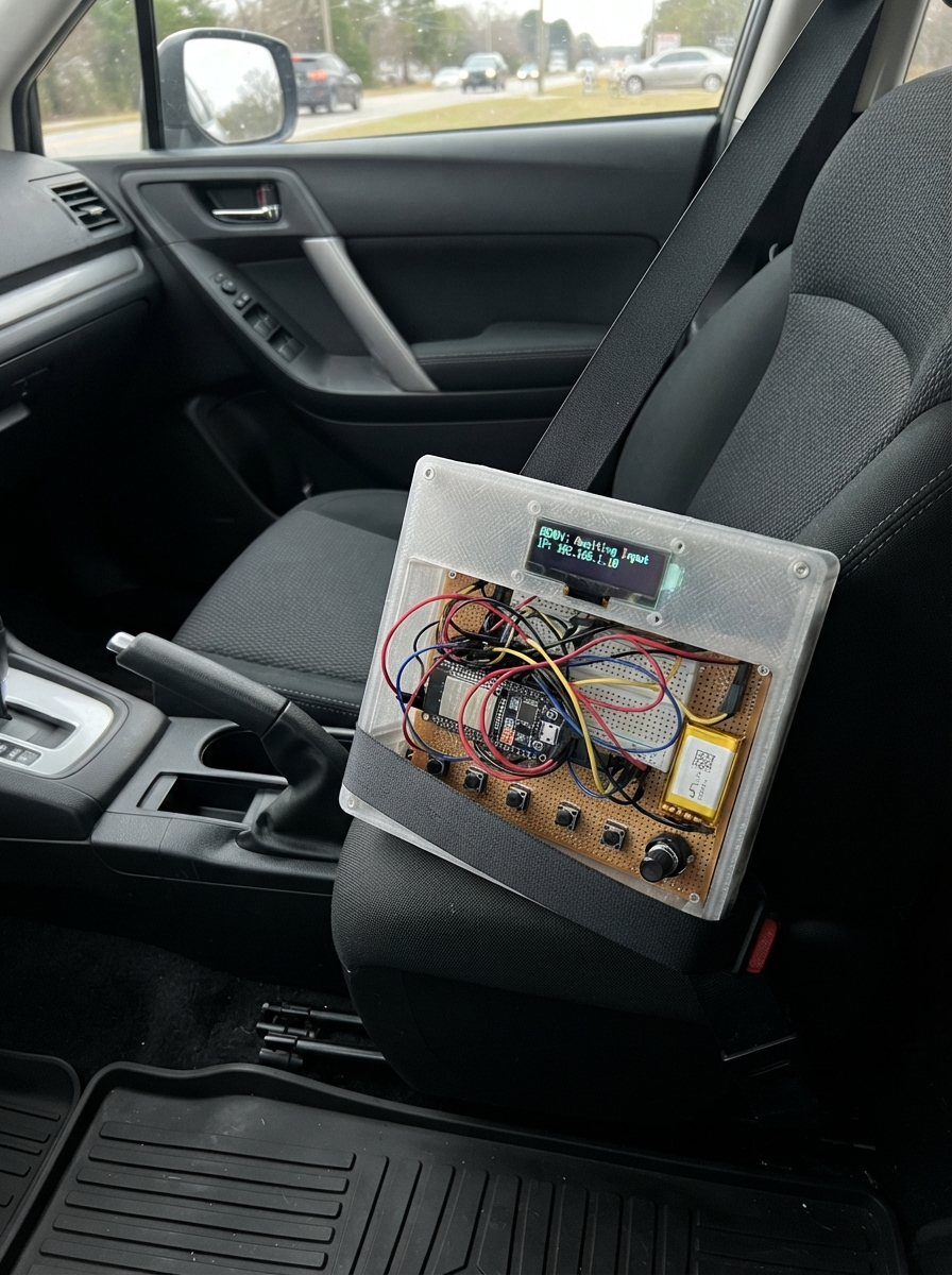
This project builds a real-time football/soccer event tagger using an ESP32 microcontroller, letting you log match events with team, player number, and timestamp data. The tagger features an OLED display for live feedback, a rotary encoder to select teams and player numbers, and a push button to mark events as they happen during play.
The guide provides a complete wiring diagram, parts list, and step-by-step assembly instructions to connect the SSD1306 OLED screen, KY-040 rotary encoder, and push button to the ESP32. The included firmware runs a local web server that broadcasts tagged events in JSON format, making it easy to integrate with video analysis software or logging systems for post-match review.
Wiring diagram

Gather all the parts
Assemble it in 5 steps
1. Place the board and modules
Put the ESP32 DevKit v1, the OLED screen, the rotary knob module, and the TAG push button on a non-metallic work surface or in a small enclosure. Leave the ESP32 USB socket reachable so it can be powered and flashed.
- Keep the labels on each small module facing up; this makes the printed pin names easy to follow.
- Do not connect the ESP32 to USB while moving loose power wires; a misplaced wire can short the board.
2. Wire the small screen
Connect OLED VCC to ESP32 3V3 (power), OLED GND to ESP32 GND (ground), OLED SDA to GPIO21 (data), and OLED SCL to GPIO22 (clock). These four wires let the screen show the current team, player, and clip state.
- Use short jumper wires and make sure VCC and GND follow the labels printed on the screen board.
- Make sure VCC and GND are not swapped — swapped power can damage the screen.
3. Wire the selector knob
Connect the KY-040 VCC pin to ESP32 3V3 (power), GND to ESP32 GND (ground), CLK to GPIO32 (turn signal), DT to GPIO33 (turn direction), and SW to GPIO27 (knob press). Turning chooses player 1 through 11; pressing switches Home and Away.
- The knob module is powered from 3.3V so its signal wires stay safe for the ESP32.
- Do not use the ESP32 5V/VIN pin for the knob module; its signal outputs could then be too high for the ESP32.
4. Wire the event button
Connect one leg of the TAG push button to ESP32 GPIO25 (signal) and the other leg to ESP32 GND (ground). A quick tap adds a match marker; holding it for about one second starts or stops a clip marker.
- For a four-leg tactile button, use two legs on opposite sides rather than two legs beside each other; legs on the same side are already joined inside the button.
- If taps do nothing, move one wire to the button leg diagonally opposite; using two joined legs does not create a button press.
5. Power and use the tagger
Check each connection once, then plug the ESP32 into USB. The controller creates the Wi-Fi network named MatchTagger; its password is sideline2026. Connect the video-analysis computer or tablet to that network and read its status at http://192.168.4.1/status or add a manual tag with http://192.168.4.1/tag?type=goal.
- A video-analysis application can poll /status or request /tag and pair each returned timestamp with its own match-video clock.
- This device creates a local sideline Wi-Fi network; it does not automatically forward tags to an internet service until the analysis platform connects to its local endpoint.
Review all connections
1. Connections between "oled_display" and "ESP32"
2. Connections between "selector_encoder" and "ESP32"
3. Connections between "tag_button" and "ESP32"
Deploy the firmware
#include <Arduino.h>
#include <Wire.h>
#include <WiFi.h>
#include <WebServer.h>
#include <Adafruit_GFX.h>
#include <Adafruit_SSD1306.h>


// Forward declarations
String selectedLabel();
String eventJson(const String &eventType);
void handleStatus();
void handleTag();
void drawScreen();
void emitLocalEvent(const String &type);
void readEncoder();
void readTagButton();

constexpr int OLED_SDA = 21;
constexpr int OLED_SCL = 22;
constexpr int ENC_CLK = 32;
constexpr int ENC_DT = 33;
constexpr int ENC_SW = 27;
constexpr int TAG_BUTTON = 25;
constexpr uint8_t SCREEN_WIDTH = 128;
constexpr uint8_t SCREEN_HEIGHT = 64;
constexpr char AP_SSID[] = "MatchTagger";
constexpr char AP_PASSWORD[] = "sideline2026";

Adafruit_SSD1306 display(SCREEN_WIDTH, SCREEN_HEIGHT, &Wire, -1);
WebServer server(80);

bool homeTeam = true;
int playerNumber = 1;
bool clipOpen = false;
int lastEncoderClock = HIGH;
bool lastEncoderButton = HIGH;
bool lastTagButton = HIGH;
unsigned long encoderButtonChangedAt = 0;
unsigned long tagButtonPressedAt = 0;
unsigned long lastScreenUpdate = 0;
String lastEvent = "Ready";

String selectedLabel() {
  return String(homeTeam ? "Home" : "Away") + " #" + String(playerNumber);
}

String eventJson(const String &eventType) {
  return String("{\"event\":\"") + eventType +
         "\",\"team\":\"" + (homeTeam ? "home" : "away") +
         "\",\"player\":" + String(playerNumber) +
         ",\"timestamp_ms\":" + String(millis()) +
         ",\"clip_open\":" + (clipOpen ? "true" : "false") + "}";
}

void handleStatus() {
  String json = String("{\"device\":\"football-sideline-tagger\",\"selected\":\"") + selectedLabel() +
                "\",\"team\":\"" + (homeTeam ? "home" : "away") +
                "\",\"player\":" + String(playerNumber) +
                ",\"clip_open\":" + (clipOpen ? "true" : "false") +
                ",\"last_event\":\"" + lastEvent + "\",\"timestamp_ms\":" + String(millis()) + "}";
  server.send(200, "application/json", json);
}

void handleTag() {
  String type = server.hasArg("type") ? server.arg("type") : "manual_tag";
  lastEvent = type;
  server.send(200, "application/json", eventJson(type));
}

void drawScreen() {
  display.clearDisplay();
  display.setTextColor(SSD1306_WHITE);
  display.setTextSize(1);
  display.setCursor(0, 0);
  display.println("MATCH TAGGER");
  display.drawLine(0, 10, 127, 10, SSD1306_WHITE);
  display.setTextSize(2);
  display.setCursor(0, 16);
  display.println(homeTeam ? "HOME" : "AWAY");
  display.setCursor(0, 35);
  display.print("PLAYER ");
  display.println(playerNumber);
  display.setTextSize(1);
  display.setCursor(0, 55);
  display.print(clipOpen ? "CLIP RECORDING" : "Tap TAG / hold clip");
  display.display();
}

void emitLocalEvent(const String &type) {
  lastEvent = type;
  Serial.println(eventJson(type));
}

void readEncoder() {
  int clockState = digitalRead(ENC_CLK);
  if (clockState != lastEncoderClock && clockState == LOW) {
    if (digitalRead(ENC_DT) != clockState) {
      playerNumber++;
      if (playerNumber > 11) playerNumber = 1;
    } else {
      playerNumber--;
      if (playerNumber < 1) playerNumber = 11;
    }
    lastEvent = "selection_changed";
  }
  lastEncoderClock = clockState;

  bool encoderPressed = digitalRead(ENC_SW) == LOW;
  if (encoderPressed && !lastEncoderButton && millis() - encoderButtonChangedAt > 180) {
    homeTeam = !homeTeam;
    lastEvent = "team_changed";
    encoderButtonChangedAt = millis();
  }
  lastEncoderButton = encoderPressed;
}

void readTagButton() {
  bool pressed = digitalRead(TAG_BUTTON) == LOW;
  if (pressed && !lastTagButton) {
    tagButtonPressedAt = millis();
  }
  if (!pressed && lastTagButton) {
    unsigned long heldFor = millis() - tagButtonPressedAt;
    if (heldFor >= 700) {
      clipOpen = !clipOpen;
      emitLocalEvent(clipOpen ? "clip_start" : "clip_stop");
    } else {
      emitLocalEvent("match_tag");
    }
  }
  lastTagButton = pressed;
}

void setup() {
  Serial.begin(115200);
  pinMode(ENC_CLK, INPUT_PULLUP);
  pinMode(ENC_DT, INPUT_PULLUP);
  pinMode(ENC_SW, INPUT_PULLUP);
  pinMode(TAG_BUTTON, INPUT_PULLUP);

  Wire.begin(OLED_SDA, OLED_SCL);
  if (!display.begin(SSD1306_SWITCHCAPVCC, 0x3C)) {
    Serial.println("SSD1306 allocation failed");
    while (true) delay(1000);
  }

  WiFi.mode(WIFI_AP);
  WiFi.softAP(AP_SSID, AP_PASSWORD);
  server.on("/status", HTTP_GET, handleStatus);
  server.on("/tag", HTTP_POST, handleTag);
  server.on("/tag", HTTP_GET, handleTag);
  server.begin();

  Serial.print("Tagger access point: ");
  Serial.println(WiFi.softAPIP());
  drawScreen();
}

void loop() {
  server.handleClient();
  readEncoder();
  readTagButton();
  if (millis() - lastScreenUpdate >= 100) {
    drawScreen();
    lastScreenUpdate = millis();
  }
}
Remix this project
Make it yours in one click
Open a full copy of this project in your own Schematik workspace — diagram, code, parts, and assembly steps included. Swap the sensor, add features, or redesign the whole thing with AI. The author's original stays untouched.