Schematik build
How to Build a Plant Disco Guardian with ESP32
A plant monitor that celebrates watering with lights and sound
What you'll build
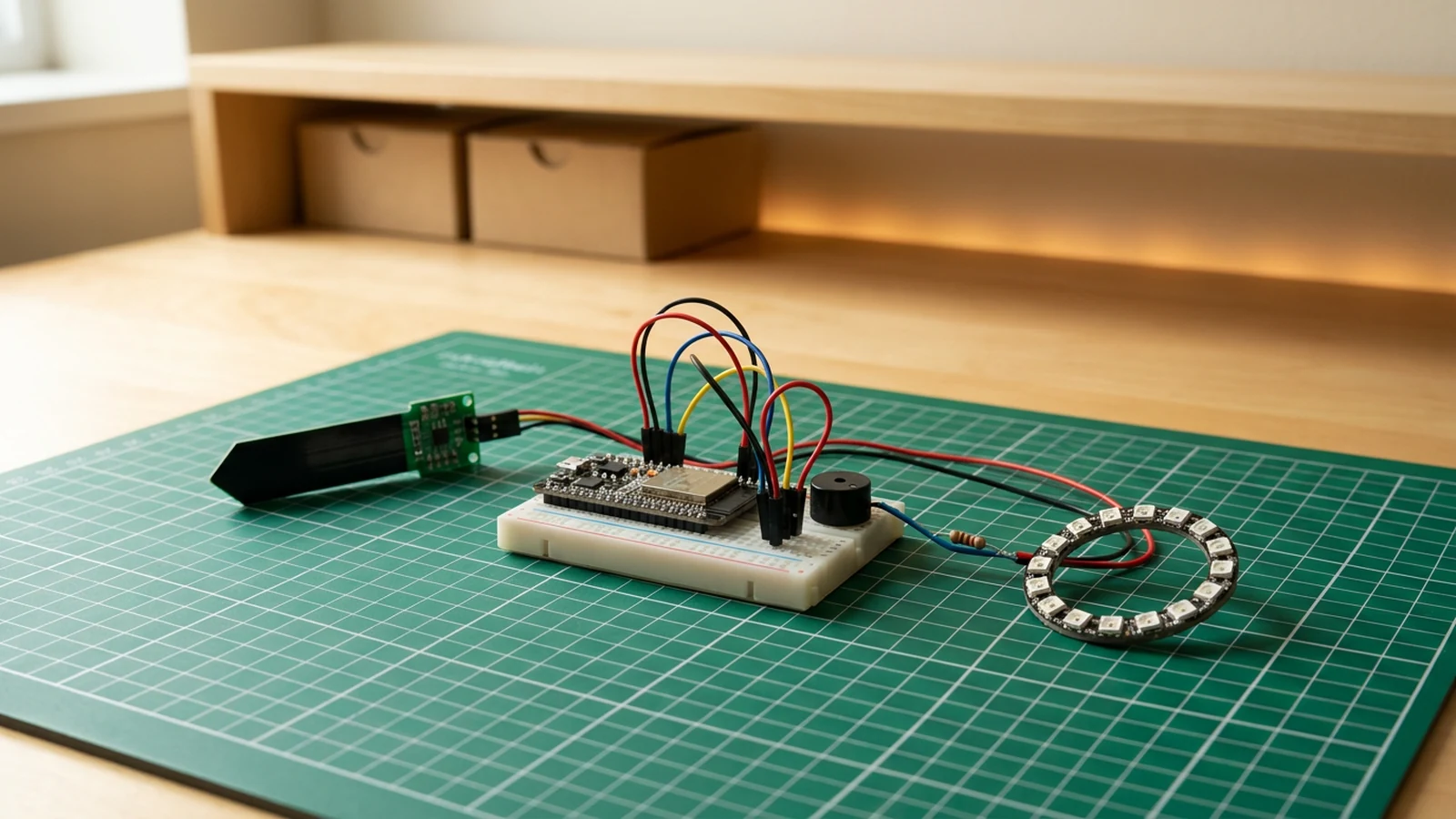
This guide shows you how to build a Plant Disco Guardian -- an ESP32-based soil moisture monitor that alerts you when your plant is thirsty and runs a brief light and sound celebration when you water it. A capacitive soil moisture sensor continuously reads the hydration level. When it drops below a configurable threshold, a WS2812B LED ring glows red and the buzzer emits a periodic chirp. When you water the plant and moisture rises back above the threshold, the guardian runs a rainbow chasing animation and a short victory melody before returning to its calm idle glow.
The project teaches you how to read an analogue capacitive sensor on the ESP32's ADC, apply hysteresis-based threshold logic to avoid false triggers when moisture hovers near the boundary, and drive a 12-LED WS2812B ring through the FastLED library. The disco celebration sequence chains multiple animation patterns using non-blocking timers so the main loop stays responsive throughout.
When the build is complete you have a self-contained monitor that runs from any USB supply. The threshold constants are easy to tune for different soil types and pot sizes, and the code is structured so you can add new animation routines or extend it with Wi-Fi logging. If you want to explore more FastLED animation techniques, the gesture-controlled mood lamp builds on the same library with hand-wave interaction.
What you are building
This build has a specific scope. Knowing what is and is not included helps you decide whether to extend it later.
- Read raw analogue moisture values from the Capacitive Soil Moisture Sensor on GPIO 34 and compare them against two configurable thresholds.
- Drive the WS2812B LED Ring with a calm idle colour when moisture is normal, switch to a solid red alert when the soil is dry.
- Sound a short periodic chirp on the Piezo Buzzer when the dry alert is active.
- Trigger a rainbow chase animation and a short victory melody when moisture recovers above the wet threshold, running the celebration for
DISCO_DURATIONmilliseconds before returning to idle. - Print moisture readings and state changes to Serial Monitor at 115200 baud for calibration and debugging.
Out of scope: Wi-Fi, push notifications, moisture data logging, multiple sensor support, and battery power management. These are reasonable extensions but are not part of this guide.
Upload and calibrate
Install libraries in the Arduino IDE Library Manager before opening the sketch:
FastLED(by Daniel Garcia)
Pin and threshold constants are near the top of the sketch:
#define SOIL_PIN        34
#define LED_PIN          4
#define BUZZER_PIN      26
#define NUM_LEDS        12
#define DRY_THRESHOLD 2600   // above this value = dry alert
#define WET_THRESHOLD 2200   // below this value = watered, trigger disco
#define DISCO_DURATION 5000  // celebration length in milliseconds
The sensor produces lower ADC values in wet soil and higher values in dry soil. DRY_THRESHOLD and WET_THRESHOLD are starting points; calibrate them for your specific sensor and soil mix by watching the Serial Monitor readings with the probe in dry soil, then in freshly watered soil, and adjusting the constants to sit comfortably between those two readings.
Upload: select your ESP32 board and port, then click Upload. Open the Serial Monitor at 115200 baud.
Expected Serial Monitor output:
Plant Disco Guardian ready
Moisture: 2860  State: DRY
Moisture: 2820  State: DRY
Moisture: 1510  State: DISCO
Moisture: 1650  State: IDLE
After the "Plant Disco Guardian ready" message, readings appear once per second. This starter targets the common capacitive module polarity where dry soil reads high and wet soil reads low. Record both values for your exact sensor, then place DRY_THRESHOLD below the dry reading and WET_THRESHOLD above the wet reading while keeping a clear hysteresis gap.
Troubleshooting
- LED ring stays off or flickers randomly. Confirm the ring and 74AHCT125 use the regulated 5 V rail, all grounds are shared, and the 220 Ω resistor sits between 1Y and DIN.
- Moisture readings are stuck at 4095 or 0. GPIO 34 is not connected to the sensor SIG pin, or the sensor VCC is not powered. Verify all three sensor wires (VCC, GND, SIG) are seated firmly.
- Disco never triggers after watering. Measure the freshly watered value, then set
WET_THRESHOLDabout 50 counts above it while keeping it belowDRY_THRESHOLD. The firmware triggers when the reading falls below this threshold. - Dry alert triggers even with wet soil. Measure the dry-soil value, then set
DRY_THRESHOLDabout 50 counts below it while keeping it aboveWET_THRESHOLD. Do not derive the dry threshold from the wet reading. - Buzzer makes no sound. GPIO 26 is not a PWM-capable pin on all ESP32 board variants. If you hear nothing, try moving the buzzer wire to GPIO 25 and updating
BUZZER_PINin the sketch. - Serial Monitor shows garbled characters. The baud rate is not set to 115200. Change it in the Serial Monitor dropdown and press the reset button on the ESP32.
Going further
The most practical extension is replacing the single threshold chirp with a graduated alert. Because SOIL_PIN gives a continuous analogue value, you can map moisture level to LED colour on a gradient -- green for well-watered, yellow for borderline, red for dry -- without adding any hardware. The FastLED CHSV colour model makes this straightforward: map the raw ADC reading to a hue value and call fill_solid.
A second direction is adding Wi-Fi so the ESP32 posts readings to a home automation system whenever the state changes. The ESP32's built-in Wi-Fi can send an HTTP POST to Home Assistant, a simple MQTT broker, or a webhook in a few dozen lines alongside the existing sensor and LED code. Because the state machine is already cleanly separated in the sketch, the networking layer drops in without restructuring the core logic.
Wiring diagram
Gather all the parts
Assemble it in 4 steps
1. Wire the low-voltage sensor and controls
Power the capacitive soil sensor from ESP32 3V3 and connect its analogue output to input-only GPIO34. Connect the passive buzzer signal to GPIO26 and its other lead to GND.
2. Build the regulated 5 V LED rail
Plug the 5 V USB-C supply into the socket breakout. Connect breakout VBUS/5V to WS2812B LED ring 5V and 74AHCT125 VCC. Connect breakout GND, ESP32 GND, WS2812B LED ring GND, and 74AHCT125 GND together. Place the bulk capacitor across 5 V and GND at the LEDs, observing polarity. Tie unused inputs 2A, 3A, and 4A to GND and unused enables 2OE, 3OE, and 4OE to 5 V.
- Unplug the supply while wiring. Verify 5 V polarity with a multimeter before connecting the LEDs or ESP32.
3. Buffer the LED data signal
Connect ESP32 GPIO4 to 74AHCT125 input 1A, tie 1OE to GND, and connect output 1Y through the 220 Ω resistor to WS2812B LED ring DIN. Do not connect GPIO4 directly to DIN. Tie unused inputs 2A, 3A, and 4A to GND and unused enables 2OE, 3OE, and 4OE to 5 V.
4. Upload, test, and calibrate
Upload the sketch, open Serial Monitor at 115200 baud, verify every input and output, then perform the calibration described in the guide before enclosing the project.
Review all connections
1. Connections between "plant-buzzer-1" and "ESP32"
2. Connections between "plant-disco-guardian-bulk-capacitor-1" and "ESP32"
3. Connections between "plant-disco-guardian-led-data-resistor-1" and "ESP32"
4. Connections between "plant-disco-guardian-logic-level-shifter-1" and "ESP32"
5. Connections between "plant-disco-guardian-regulated-5v-supply-1" and "ESP32"
6. Connections between "plant-disco-guardian-usb-c-power-breakout-1" and "ESP32"
7. Connections between "plant-led-ring-1" and "ESP32"
8. Connections between "soil-sensor-1" and "ESP32"
Deploy the firmware
#include <FastLED.h>

#define SOIL_PIN 34
#define LED_PIN 4
#define NUM_LEDS 12
#define BUZZER_PIN 26

CRGB leds[NUM_LEDS];

const int DRY_THRESHOLD = 2600;
const int WET_THRESHOLD = 2200;

bool wasDry = false;
unsigned long discoEndMs = 0;
const unsigned long DISCO_DURATION = 5000;

int smoothRead(int pin, int samples = 8) {
  long sum = 0;
  for (int i = 0; i < samples; i++) {
    sum += analogRead(pin);
    delay(2);
  }
  return sum / samples;
}

void discoPattern() {
  for (int i = 0; i < NUM_LEDS; i++) {
    leds[i] = CHSV((millis() / 6 + i * 21) % 255, 255, 200);
  }
}

void warningPattern() {
  uint8_t pulse = beatsin8(30, 60, 200);
  fill_solid(leds, NUM_LEDS, CRGB(pulse, 0, 0));
}

void idlePattern() {
  uint8_t glow = beatsin8(15, 40, 120);
  fill_solid(leds, NUM_LEDS, CRGB(0, glow, glow / 3));
}

void setup() {
  Serial.begin(115200);
  delay(100);
  FastLED.addLeds<NEOPIXEL, LED_PIN>(leds, NUM_LEDS);
  FastLED.setBrightness(140);
  pinMode(BUZZER_PIN, OUTPUT);
  Serial.println("Plant Disco Guardian ready");
}

void loop() {
  int moisture = smoothRead(SOIL_PIN);
  bool isDry = moisture > DRY_THRESHOLD;
  bool isWet = moisture < WET_THRESHOLD;

  if (isDry) wasDry = true;

  if (wasDry && isWet) {
    discoEndMs = millis() + DISCO_DURATION;
    tone(BUZZER_PIN, 1800, 100);
    delay(110);
    tone(BUZZER_PIN, 2200, 100);
    delay(110);
    tone(BUZZER_PIN, 2600, 150);
    Serial.println("DISCO TIME!");
    wasDry = false;
  }

  bool discoMode = millis() < discoEndMs;

  if (discoMode) {
    discoPattern();
  } else if (isDry) {
    warningPattern();
    if ((millis() / 3000) % 2 == 0) {
      tone(BUZZER_PIN, 900, 80);
    }
  } else {
    idlePattern();
  }

  FastLED.show();

  Serial.printf("Moisture: %d | %s\n", moisture,
    discoMode ? "DISCO" : isDry ? "DRY" : "OK");
  delay(discoMode ? 30 : 200);
}
Remix this project
Make it yours in one click
Open a full copy of this project in your own Schematik workspace — diagram, code, parts, and assembly steps included. Swap the sensor, add features, or redesign the whole thing with AI. The author's original stays untouched.
Related projects
How to Build a Gesture-Controlled Mood Lamp with ESP32
ESP32 · Beginner · 45 minutes · July 22, 2026Schematik
How to Build a Cosmic Critter Pet with Raspberry Pi Pico
Raspberry Pi Pico · Beginner · 40 minutes · July 22, 2026Schematik
How to Build a Rocket Launch Alarm Clock with ESP32
ESP32 · Beginner · 40 minutes · July 22, 2026Schematik