Schematik build
How to Build a Laser Harp Synth with ESP32
Break light beams to trigger notes and visual feedback
What you'll build
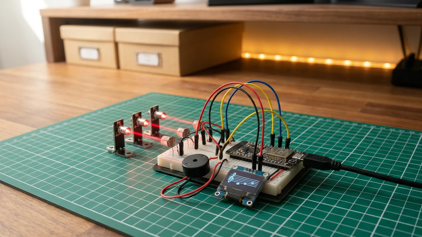
Build a three-beam laser harp using an ESP32, three LDR voltage dividers, a piezo speaker, and an SSD1306 OLED display. Mount three laser diodes or bright LEDs opposite the LDRs so each sensor sits in a beam of light. Break a beam with your hand and the ESP32 detects the drop in voltage, plays the corresponding note through the speaker, and shows which note is active on the OLED. All three beams can be broken simultaneously to play a chord.
The instrument auto-calibrates at startup by averaging 20 ADC readings across all three channels while the beams are unbroken. A HYSTERESIS constant keeps notes from flickering on and off when a hand is near but not quite breaking the beam. Notes are C5, E5, and G5 — a major triad — driven by the ESP32's tone() function on the piezo.
The firmware has four jobs: auto-calibrate baseline light levels for all three LDRs at boot; detect beam breaks using a HYSTERESIS threshold compared to each baseline; drive the piezo with accurate note frequencies using tone(); and render active notes on the SSD1306 OLED display in real time. Adding octave shifting, a pentatonic scale, or a richer audio output stage are natural next steps once the three-beam core is working.
Upload and calibrate
Flash the sketch from Schematik and open Serial Monitor at 115200 baud. Keep all three beams unbroken during the first two seconds of boot — the firmware prints Baselines: <n1> <n2> <n3> as it calibrates. A typical indoor baseline is in the 2500–3500 range. If any channel reads below 1000 with the beam intact, suspect loose beam alignment or a missing pull-down resistor.
After calibration, wave your hand through each beam in turn. Serial Monitor shows the live ADC reading alongside the baseline. If beams trigger too easily in a bright room, increase HYSTERESIS in the code (try 400 instead of 200). If they are slow to trigger, decrease it. Notes played are C5 (523 Hz), E5 (659 Hz), and G5 (784 Hz). The OLED shows live readings and the active note name.
Troubleshooting
- One beam never triggers. Read the raw ADC value from Serial Monitor. If it never drops when the beam is broken, check that the LDR is facing the light source, the voltage divider is wired correctly, and the pull-down resistor is present.
- Constant false triggers in a bright room. Ambient light is raising the LDR reading above the break threshold. Increase
HYSTERESISor shield the LDRs with a small tube or hood over each sensor. - OLED stays blank. The default I2C address is 0x3C. Some modules use 0x3D — check the label on your board and update the
begin()call if needed. - No sound from the piezo. Confirm GPIO 25 is wired to the piezo signal lead and GND to the other lead. A passive piezo buzzer works with
tone(); an active buzzer only needs DC and will not respond to the PWM signal. - All three baselines read near zero. The 3.3 V supply to the voltage dividers is missing. Confirm the VCC connection on all three dividers.
Going further
The three-note major triad is the simplest musical entry point. Swap the frequency array for a pentatonic scale or any other set of notes to change the instrument's character. Adding a fourth LDR on GPIO 33 extends the range to a full tetrachord. For noticeably richer sound, replace the piezo with an I2S DAC and amplifier — the Hermes Voice Satellite uses the MAX98357A I2S amp and covers the wiring pattern in detail.
Wiring diagram
Gather all the parts
Assemble it in 4 steps
1. Build the LDR voltage dividers
For each LDR, create a voltage divider with a 10 kΩ pull-down resistor. Connect the middle point to GPIO34, GPIO35, and GPIO32. Power each divider from 3.3V.
- Use identical resistor values for all three channels so calibration is consistent.
- GPIO34, 35 are input-only on the ESP32 — this is fine for analog reads.
2. Set up the light sources
Mount three laser diodes or bright LEDs opposite the LDRs. Align each beam to hit its corresponding sensor directly.
- Use a cardboard frame with holes to keep beams aligned.
- Never look directly into laser beams.
3. Connect speaker and display
Wire piezo speaker signal to GPIO25 (other lead to GND). Connect OLED VCC to 3.3V, GND to ground, SDA to GPIO21, SCL to GPIO22.
- A small amplifier module between the ESP32 and speaker dramatically improves sound quality.
4. Calibrate and play
Flash the sketch. The harp auto-calibrates on startup — keep all beams unbroken during the first 2 seconds. Then wave your hand through the beams to play C5, E5, and G5.
- Adjust the HYSTERESIS value in code if the sensors trigger too easily in bright rooms.
Review all connections
1. Connections between "laser-harp-synth-220-ohm-resistor-1" and "ESP32"
2. Connections between "laser-ldr-1" and "ESP32"
3. Connections between "laser-modules-3" and "ESP32"
4. Connections between "laser-oled-1" and "ESP32"
5. Connections between "laser-speaker-1" and "ESP32"
Deploy the firmware
#include <Wire.h>
#include <Adafruit_SSD1306.h>

#define LDR_1 34
#define LDR_2 35
#define LDR_3 32
#define BUZZER_PIN 25
#define SDA_PIN 21
#define SCL_PIN 22

Adafruit_SSD1306 display(128, 64, &Wire, -1);

int baseline1 = 0, baseline2 = 0, baseline3 = 0;
const int HYSTERESIS = 200;
const char* noteNames[] = {"C5", "E5", "G5"};
const int noteFreqs[] = {523, 659, 784};

void calibrate() {
  long sum1 = 0, sum2 = 0, sum3 = 0;
  for (int i = 0; i < 20; i++) {
    sum1 += analogRead(LDR_1);
    sum2 += analogRead(LDR_2);
    sum3 += analogRead(LDR_3);
    delay(10);
  }
  baseline1 = sum1 / 20;
  baseline2 = sum2 / 20;
  baseline3 = sum3 / 20;
}

void setup() {
  Serial.begin(115200);
  delay(100);

  Wire.begin(SDA_PIN, SCL_PIN);
  display.begin(SSD1306_SWITCHCAPVCC, 0x3C);
  display.setTextSize(1);
  display.setTextColor(SSD1306_WHITE);
  pinMode(BUZZER_PIN, OUTPUT);

  display.clearDisplay();
  display.setCursor(0, 24);
  display.println("Calibrating...");
  display.display();
  calibrate();

  Serial.printf("Baselines: %d %d %d\n", baseline1, baseline2, baseline3);
}

void loop() {
  int n1 = analogRead(LDR_1);
  int n2 = analogRead(LDR_2);
  int n3 = analogRead(LDR_3);

  bool beams[] = {
    n1 < baseline1 - HYSTERESIS,
    n2 < baseline2 - HYSTERESIS,
    n3 < baseline3 - HYSTERESIS,
  };

  int activeNote = -1;
  for (int i = 0; i < 3; i++) {
    if (beams[i]) { activeNote = i; break; }
  }

  if (activeNote >= 0) {
    tone(BUZZER_PIN, noteFreqs[activeNote], 40);
  } else {
    noTone(BUZZER_PIN);
  }

  display.clearDisplay();
  display.setCursor(0, 0);
  display.println("-- Laser Harp --");
  display.println();
  for (int i = 0; i < 3; i++) {
    display.printf("L%d: %4d %s %s\n", i + 1,
      i == 0 ? n1 : i == 1 ? n2 : n3,
      beams[i] ? ">>>" : "   ",
      beams[i] ? noteNames[i] : ""
    );
  }
  display.println();
  if (activeNote >= 0) {
    display.printf("Playing: %s (%dHz)", noteNames[activeNote], noteFreqs[activeNote]);
  } else {
    display.println("No beam broken");
  }
  display.display();
  delay(20);
}
Remix this project
Make it yours in one click
Open a full copy of this project in your own Schematik workspace — diagram, code, parts, and assembly steps included. Swap the sensor, add features, or redesign the whole thing with AI. The author's original stays untouched.
Related projects
How to Build a Gesture-Controlled Mood Lamp with ESP32
ESP32 · Beginner · 45 minutes · July 22, 2026Schematik
How to Build an Arcade Reaction Tower with ESP32
ESP32 · Beginner · 40 minutes · June 12, 2026Schematik
How to Build a Plant Disco Guardian with ESP32
ESP32 · Beginner · 35 minutes · July 22, 2026Schematik