Schematik build
Build A Heart Rate Spo2 Monitor Esp32 Gy-max3010
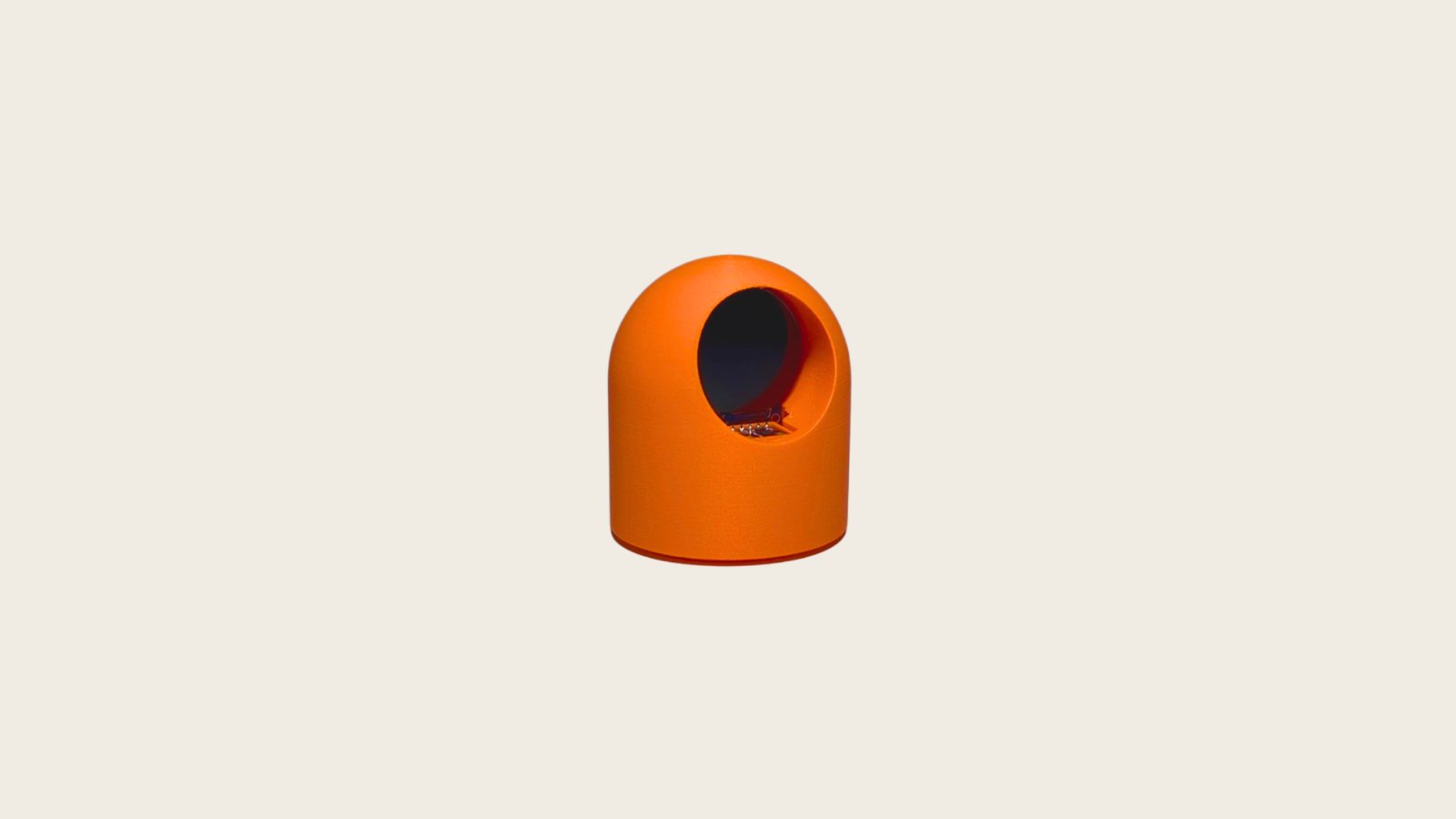
This project builds a wearable heart rate and blood oxygen (SpO2) monitor using an ESP32 microcontroller and MAX30102 optical sensor. The round 1.28-inch GC9A01 display provides real-time readings with a compact form factor suitable for wrist-mounted applications.
The guide includes a complete wiring diagram showing I2C connections between the MAX30102 and ESP32, a full parts list, pre-built firmware with heart rate averaging and SpO2 calculation algorithms, and step-by-step assembly instructions. After wiring and flashing the firmware via Schematik Deploy, the monitor detects finger placement and continuously outputs BPM and oxygen saturation levels to both the display and serial output.
Wiring diagram

Gather all the parts
Assemble it in 4 steps
1. Prepare (everything unpowered)
Unplug USB or battery. Clear the bench and keep the Pins tab open — every connection below follows that table. Board: Espressif ESP32-S3-DevKitC-1-N8 (8 MB QD, No PSRAM).
- Use different wire colors for VCC, GND, and signals if you have them
- Do not power the board until wiring matches the pin map
2. Wire MAX30102
Wire MAX30102 (max30102_0) like this: MAX30102 · VCC → 3V3 [power] MAX30102 · GND → GND [ground] MAX30102 · SDA → GPIO8 [i2c] MAX30102 · SCL → GPIO9 [i2c] MAX30102 · INT → GPIO1 [digital] Give each jumper a light tug so loose Dupont connectors show up now, not after flashing.
3. Flash firmware with Schematik Deploy
Connect the board by USB. In Schematik, open Deploy and click Deploy to compile and flash the sketch to your board. Use Chrome or Edge for Web Serial. When the browser asks, choose your board's serial port.
- Skim the Code tab before uploading
- Schematik passes the listed libraries into the compile step for you
4. Power on and verify
After upload, the board resets and starts running the sketch. Open the serial monitor or watch the LEDs and sensors for the behavior the code describes — this is the fun first proof that the build is alive. If anything gets hot or smells wrong, unplug USB immediately.
- If the board resets in a loop, recheck GND and 3.3V/5V levels
Review all connections
1. Connections between "max30102_0" and "Arduino"
2. Connections between "gc9a01_0" and "Arduino"
Deploy the firmware
#include <Arduino.h>
// Heart Rate & SpO2 Monitor
// ESP32-S3 + MAX30102
// I2C on GPIO8 (SDA), GPIO9 (SCL)

#include <Wire.h>
#include <MAX30105.h>
#include <heartRate.h>
#include <spo2_algorithm.h>

// Pin definitions
#define I2C_SDA 8
#define I2C_SCL 9
#define MAX30102_INT_PIN 1

// Reporting period for serial update
#define REPORTING_PERIOD_MS 1000

// Objects
MAX30105 particleSensor;

// Heart rate averaging
#define RATE_SIZE 4
byte rates[RATE_SIZE];
byte rateSpot = 0;
long lastBeat = 0;
float beatsPerMinute = 0;
int beatAvg = 0;

// SpO2 calculation buffers (kept small for memory)
#define SPO2_BUFFER_SIZE 50
uint32_t irBuffer[SPO2_BUFFER_SIZE];
uint32_t redBuffer[SPO2_BUFFER_SIZE];
int32_t spo2Value = 0;
int8_t spo2Valid = 0;
int32_t heartRateValue = 0;
int8_t heartRateValid = 0;

// State
uint32_t lastReportTime = 0;
float lastBPM = 0.0;
int lastSpO2 = 0;
bool sensorReady = false;
uint32_t lastSpO2Calc = 0;
#define SPO2_CALC_INTERVAL_MS 5000

// Finger detection threshold
#define FINGER_THRESHOLD 50000

void setup() {
    Serial.begin(115200);
    delay(500);
    Serial.println(F("Heart Rate & SpO2 Monitor starting..."));

    // Initialize I2C with custom pins for ESP32-S3
    Wire.begin(I2C_SDA, I2C_SCL);

    // Configure interrupt pin
    pinMode(MAX30102_INT_PIN, INPUT_PULLUP);

    // Initialize MAX30102
    Serial.println(F("Initializing MAX30102..."));
    if (!particleSensor.begin(Wire, I2C_SPEED_FAST)) {
        Serial.println(F("MAX30102 init FAILED! Check wiring."));
        sensorReady = false;
    } else {
        Serial.println(F("MAX30102 init SUCCESS"));
        sensorReady = true;

        // Configure sensor for SpO2 + HR
        byte ledBrightness = 0x1F; // ~6.4mA
        byte sampleAverage = 4;
        byte ledMode = 2;         // Red + IR
        int sampleRate = 200;
        int pulseWidth = 411;
        int adcRange = 4096;

        particleSensor.setup(ledBrightness, sampleAverage, ledMode,
                             sampleRate, pulseWidth, adcRange);

        // Enable FIFO rolling
        particleSensor.enableAFULL();
    }

    lastReportTime = millis();
    lastSpO2Calc = millis();
}

void loop() {
    if (!sensorReady) {
        // Retry sensor init every 5 seconds
        static uint32_t lastRetry = 0;
        if (millis() - lastRetry > 5000) {
            Serial.println(F("Retrying MAX30102 init..."));
            if (particleSensor.begin(Wire, I2C_SPEED_FAST)) {
                Serial.println(F("MAX30102 init SUCCESS on retry"));
                sensorReady = true;
                particleSensor.setup(0x1F, 4, 2, 200, 411, 4096);
                particleSensor.enableAFULL();
            }
            lastRetry = millis();
        }
        return;
    }

    // Read IR value for heart rate detection
    long irValue = particleSensor.getIR();

    // Check if finger is on sensor
    if (irValue > FINGER_THRESHOLD) {
        // Check for beat
        if (checkForBeat(irValue)) {
            long delta = millis() - lastBeat;
            lastBeat = millis();

            beatsPerMinute = 60.0 / (delta / 1000.0);

            if (beatsPerMinute > 20 && beatsPerMinute < 255) {
                rates[rateSpot++ % RATE_SIZE] = (byte)beatsPerMinute;

                // Compute average
                beatAvg = 0;
                byte count = min((byte)(rateSpot), (byte)RATE_SIZE);
                for (byte x = 0; x < count; x++) {
                    beatAvg += rates[x];
                }
                beatAvg /= count;
            }
        }

        // Periodically compute SpO2
        if (millis() - lastSpO2Calc > SPO2_CALC_INTERVAL_MS) {
            lastSpO2Calc = millis();

            // Collect samples for SpO2 calculation
            for (int i = 0; i < SPO2_BUFFER_SIZE; i++) {
                while (!particleSensor.available())
                    particleSensor.check();

                redBuffer[i] = particleSensor.getRed();
                irBuffer[i] = particleSensor.getIR();
                particleSensor.nextSample();
            }

            // Calculate SpO2
            maxim_heart_rate_and_oxygen_saturation(
                irBuffer, SPO2_BUFFER_SIZE, redBuffer,
                &spo2Value, &spo2Valid,
                &heartRateValue, &heartRateValid);

            if (spo2Valid && spo2Value > 0 && spo2Value <= 100) {
                lastSpO2 = spo2Value;
            }
        }

        lastBPM = beatAvg;
    } else {
        // No finger detected
        lastBPM = 0;
        lastSpO2 = 0;
        beatAvg = 0;
        rateSpot = 0;
    }

    // Report to serial periodically
    if (millis() - lastReportTime > REPORTING_PERIOD_MS) {
        if (irValue > FINGER_THRESHOLD) {
            Serial.print(F("BPM: "));
            Serial.print(lastBPM, 1);
            Serial.print(F("  Avg BPM: "));
            Serial.print(beatAvg);
            Serial.print(F("  SpO2: "));
            Serial.print(lastSpO2);
            Serial.print(F("%  IR: "));
            Serial.println(irValue);
        } else {
            Serial.println(F("No finger detected. Place finger on sensor."));
        }
        lastReportTime = millis();
    }
}
Download project files
Remix this project
Make it yours in one click
Open a full copy of this project in your own Schematik workspace — diagram, code, parts, and assembly steps included. Swap the sensor, add features, or redesign the whole thing with AI. The author's original stays untouched.
Related projects
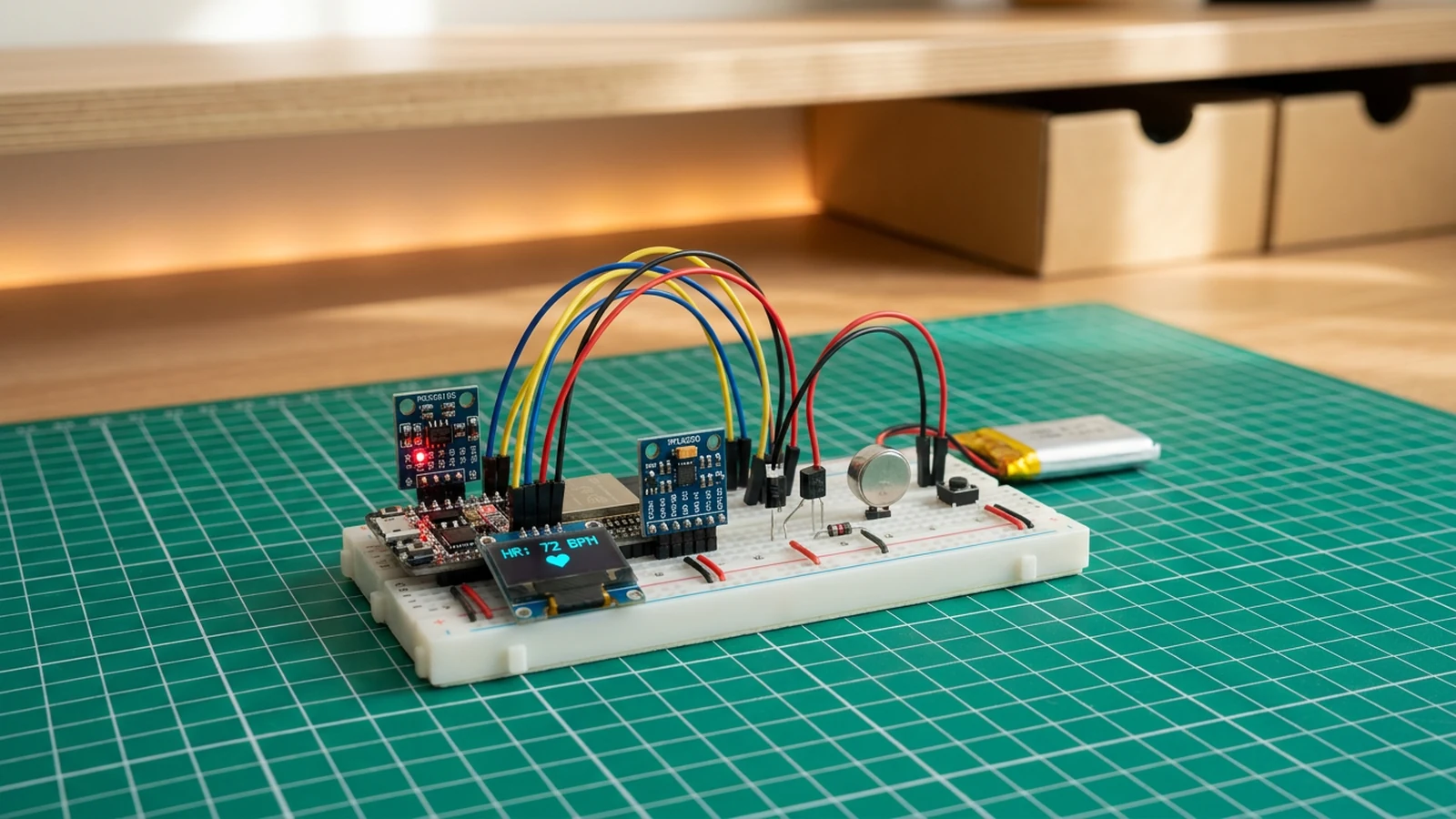
How to Build a Fitness Wristband Prototype with ESP32
ESP32 · Intermediate · 50 minutes · June 12, 2026Schematik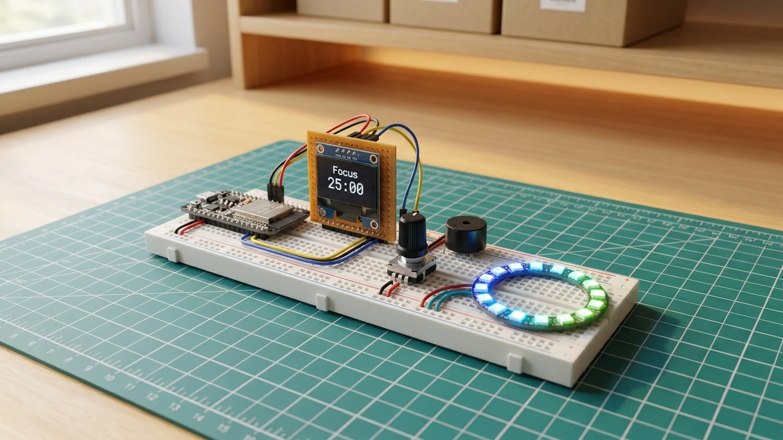
How to Build an ESP32 Pomodoro Focus Timer
ESP32 · Beginner · 45 minutes · July 22, 2026Schematik
How to Build a CO2 Room Monitor with ESP32
ESP32 · Beginner · 35 minutes · June 12, 2026Schematik