Schematik build
How to Build a Fitness Wristband Prototype with ESP32
Heart-rate sampling, step estimation, and low-power OLED display
What you'll build
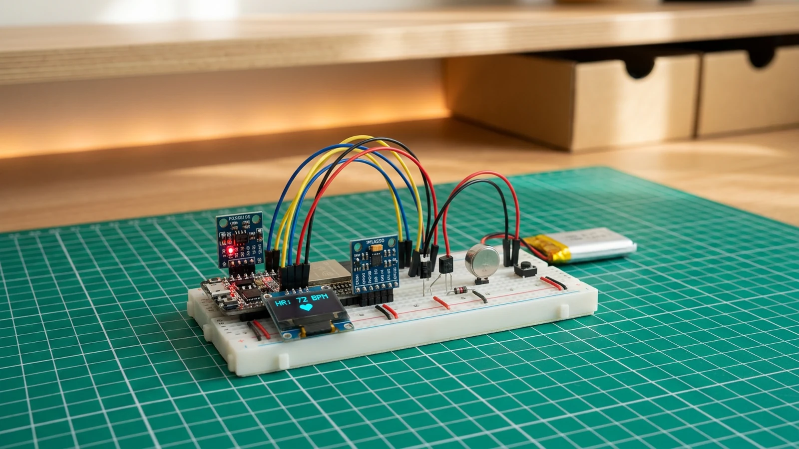
This guide takes you through building a fitness wristband prototype using an ESP32, a MAX30102 pulse oximetry and heart-rate sensor, an MPU6050 accelerometer and gyroscope, and a 0.96-inch OLED display. The wristband detects heartbeats by shining infrared light through your fingertip, counts steps using a peak-detection algorithm on the accelerometer's magnitude, and presents both metrics on the OLED. A single button cycles through three display modes: Health, Motion, and Summary. A small vibration motor buzzes at step milestones so you feel the feedback even when the screen is off.
Wearable health hardware is genuinely difficult to get right. This build gives you hands-on experience with three I2C peripherals sharing a single bus, biometric signal processing in firmware, and the transistor circuit that lets a microcontroller drive a motor without burning out a GPIO pin. The scope is deliberately bounded: one wrist, one session, something you can hold in your hand by the end of the guide.
The MPU6050 accelerometer used here also appears in the self-balancing rover, where it drives a PID control loop instead of counting steps.
What you are building
This guide covers a wristband prototype with four firmware jobs:
- Read infrared intensity from the MAX30102 and run beat detection to produce a rolling four-beat heart-rate average.
- Poll the MPU6050 accelerometer, compute the acceleration magnitude, and count steps using a threshold-and-refractory algorithm.
- Refresh a 128×64 OLED at roughly 4 FPS with mode-appropriate data: heart rate and finger status on Health mode, step count on Motion mode, and a combined summary on Summary mode.
- Drive a vibration motor via a transistor circuit — buzzing once at each 500-step milestone.
Out of scope: Bluetooth streaming, sleep-mode power management, skin temperature from the MAX30102 die-temperature register, and persistent storage. Those are all reasonable next steps, but not needed to get the wristband working.
Upload and calibrate
Install the following libraries through the Arduino Library Manager or PlatformIO before flashing:
- SparkFun MAX3010x Pulse and Proximity Sensor Library (for beat detection via
checkForBeat()) - Adafruit MPU6050
- Adafruit SSD1306
Flash the firmware and open Serial Monitor at 115200 baud. On a successful boot you should see three lines in order:
MPU6050 OK
MAX30102 OK
Wristband ready
If any line is missing, that sensor did not initialise. Check its SDA, SCL, VCC, and GND connections and confirm the I2C address matches — the MAX30102 is typically 0x57, the MPU6050 0x68, and the SSD1306 0x3C.
Key firmware constants to be aware of:
HR_INT_PIN 19— MAX30102 interrupt line. The firmware polls this pin to know when new samples are ready.VIBE_PIN 25— drives the transistor base for the motor.BTN_PIN 33— mode button, read with internal pull-up.RATE_SIZE 4— the rolling average covers the last four beat intervals. With fewer than four valid readings the displayed BPM will be zero.DISPLAY_INTERVAL 250— the OLED refreshes every 250 ms (4 FPS). Faster refresh is possible but will not improve the heart-rate reading, which is gated by actual beats.
On first boot the OLED shows the Health mode screen. With no finger on the sensor it displays "Place finger on sensor" — this is expected. The firmware considers a finger present only when the infrared reading exceeds 50,000 counts. Once you press a fingertip firmly against the MAX30102, the raw IR value climbs above that threshold within a second or two and beat detection starts. Valid beats must fall between 20 and 255 BPM to be accepted into the rolling average.
Press the button to cycle through Health → Motion → Summary modes. The Motion screen shows the live step count. Walk a few steps and watch the count increment; the motor buzzes briefly every 500 steps. If the step count runs too fast at rest, the detection threshold (accelMag > 13.0f) or the refractory period (300 ms between accepted steps) can be tuned in the firmware.
Troubleshooting
- Serial Monitor shows nothing after flashing. Confirm the baud rate is 115200. If the board resets in a loop, check that 3V3 is stable — adding a 100 µF capacitor across 3V3 and GND can help when USB power is marginal.
- "MPU6050 OK" appears but MAX30102 or SSD1306 do not. I2C devices can mask each other if a wire is shorting SDA or SCL to GND. Disconnect one sensor at a time and reflash to isolate the fault.
- Heart rate reads 0 even with a finger on the sensor. The four-beat rolling average needs four valid consecutive readings to produce a non-zero result. Hold your finger still and flat for 10–15 seconds. Excessive motion makes the IR signal too noisy for
checkForBeat()to find a peak. - Step count increments while sitting. Lower the detection threshold slightly or increase the refractory period. Tapping the board on a hard surface can also trigger the algorithm — mount or hold it loosely.
- Motor does not buzz. Check the transistor orientation (flat face vs. curved face), the base resistor, and that GPIO 25 is actually toggling. A multimeter on the collector should show near-rail voltage when
VIBE_PINis LOW and near-zero when HIGH. - OLED is blank after init message. The SSD1306 initialisation can silently succeed with a wrong I2C address and then fail to draw. Scan the bus with an I2C scanner sketch to confirm the display is at
0x3C; some modules ship at0x3D.
Going further
The most immediately useful extension is Bluetooth Low Energy broadcasting. The ESP32's built-in BLE stack can advertise heart rate and step count as standard GATT characteristics, which means any generic health app on a phone can read them without a custom companion app. The wristband firmware already has the data ready; it just needs a BLE server and notify loop on top.
For a more comfortable wearable, consider moving from a breadboard to a custom PCB or a flexible stripboard layout, and replacing USB power with a small LiPo and a TP4056 charge module. The MAX30102 also exposes a die-temperature register that gives a rough skin-temperature reading — useful as a second biometric with only a few extra lines of firmware and no additional hardware.
Wiring diagram
Gather all the parts
Assemble it in 6 steps
1. Wire the I2C health sensors
Connect the MAX30102 Heart Sensor, MPU6050 Motion Sensor, and SSD1306 OLED to the ESP32. All three share the same I2C bus: VCC → 3.3V rail, GND → GND rail, SDA → GPIO21, SCL → GPIO22. Each module can sit directly on a breadboard with its four wires run to a common rail.
- Keep the I2C wires short (under 20 cm) to avoid signal reflections on a 400 kHz bus.
- The MAX30102 and MPU6050 have different I2C addresses (0x57 and 0x68), so they coexist without any address-select jumpers.
- Use the 3.3V rail only — the ESP32 GPIOs are not 5V tolerant and most breakout boards for these sensors are 3.3V-native.
2. Add vibration motor with transistor
The Vibration Motor draws more current than a GPIO pin can safely supply, so drive it through a 2N2222 NPN transistor. Connect a 1 kΩ resistor from GPIO25 to the transistor base, the collector to the motor's negative lead, and the emitter to GND. Connect the motor's positive lead to the 3.3V rail. Place a 1N4001 flyback diode across the motor terminals (cathode toward 3.3V) to suppress voltage spikes when the motor de-energises.
- The transistor and diode are small through-hole parts — a half-sized breadboard has plenty of room.
- Never connect the motor directly to a GPIO pin. A 130-type coin motor can pull 80–100 mA, well above the 40 mA GPIO maximum, and will damage the ESP32.
3. Wire the mode button
Connect one leg of the Mode Button to GPIO33 and the other leg to GND. The firmware configures GPIO33 as INPUT_PULLUP, so no external pull-up resistor is needed. Pressing the button cycles through the three display modes: Health, Motion, and Summary.
- A 6 mm tactile switch fits neatly on a breadboard and works well for a prototype wristband form factor.
4. Check power and I2C addresses
Before uploading firmware, verify all power connections with a multimeter: 3.3V and GND should read 3.28–3.35 V across every module's VCC and GND pins. If you have an I2C scanner sketch handy, flash it first to confirm addresses 0x3C (SSD1306), 0x57 (MAX30102), and 0x68 (MPU6050) all appear on the bus.
- An I2C scanner sketch is included in the Arduino IDE under File → Examples → Wire → i2c_scanner.
- If any device is missing from the scan, re-seat its wiring before uploading the main firmware — a missing sensor will log an error to Serial but the sketch will still run.
5. Upload firmware and open Serial Monitor
Flash the firmware to the ESP32 at 115200 baud. Open the Serial Monitor and confirm you see 'MPU6050 OK', 'MAX30102 OK', and 'Wristband ready'. A short buzz from the Vibration Motor confirms the haptic path is working. If a sensor line says 'not found', check wiring on GPIO21 and GPIO22.
- Press the Mode Button once after startup to confirm display mode cycling and the 40 ms haptic buzz.
6. Test heart-rate and step detection
Place the MAX30102 sensor firmly against a fingertip. The OLED Health screen will show 'Measuring...' for a few beats, then display a stable BPM averaged over the last four beats. Walk briskly with the board and watch the step counter increment on the Health and Summary screens. Every 500 steps triggers an 80 ms buzz.
- Press the sensor flat and hold still for 10–15 seconds to let the rolling average stabilise — slight movement causes the IR signal to fluctuate and temporarily shows '--'.
- The step threshold (13 m/s² peak, 300 ms refractory) works well for a wrist mount. If steps under-count or double-count, adjust the 13.0f / 11.0f thresholds and 300 ms debounce in the code.
Review all connections
1. Connections between "1k-base-resistor" and "ESP32"
2. Connections between "max30102-1" and "ESP32"
3. Connections between "mode-btn-1" and "ESP32"
4. Connections between "vibe-1" and "ESP32"
5. Connections between "wearable-flyback-diode-1" and "ESP32"
6. Connections between "wearable-imu-1" and "ESP32"
7. Connections between "wearable-npn-driver-1" and "ESP32"
8. Connections between "wearable-oled-1" and "ESP32"
Deploy the firmware
// Fitness Wristband — ESP32 + MAX30102 + MPU6050 + SSD1306 OLED
// Heart rate uses real beat detection via SparkFun MAX3010x heartRate.h.
// The display redraws at ~4 Hz; beat sampling runs every loop() iteration
// so no beats are missed between redraws. This split is important: the
// MAX30102 FIFO fills quickly and stale reads skew timing calculations.

#include <Wire.h>
#include <Adafruit_MPU6050.h>
#include <Adafruit_Sensor.h>
#include <Adafruit_SSD1306.h>
#include <MAX30105.h>
#include "heartRate.h"

// ── Pin definitions ──────────────────────────────────────────────────────────
#define SDA_PIN     21
#define SCL_PIN     22
#define HR_INT_PIN  19
#define VIBE_PIN    25
#define BTN_PIN     33

// ── Display ──────────────────────────────────────────────────────────────────
#define SCREEN_W 128
#define SCREEN_H  64
Adafruit_SSD1306 display(SCREEN_W, SCREEN_H, &Wire, -1);

// ── Sensors ──────────────────────────────────────────────────────────────────
Adafruit_MPU6050 mpu;
MAX30105 particleSensor;

// ── Step counting ────────────────────────────────────────────────────────────
unsigned long steps       = 0;
unsigned long lastStepMs  = 0;
bool          stepHigh    = false;

// ── Display mode cycling ─────────────────────────────────────────────────────
int  displayMode    = 0;   // 0 = Health, 1 = Motion, 2 = Summary
bool btnWasPressed  = false;

// ── Heart-rate beat detection ────────────────────────────────────────────────
// Rolling average over RATE_SIZE beats for stable display.
// Fewer samples → more responsive but noisier; 4 is a good wristband trade-off.
#define RATE_SIZE 4
float beatsPerMinute          = 0.0f;
float beatAvg                 = 0.0f;
float rates[RATE_SIZE]        = {0};
byte  rateSpot                = 0;
long  lastBeatMs              = 0;

// ── OLED refresh throttle ────────────────────────────────────────────────────
// Beat sampling runs every loop(); OLED only redraws every DISPLAY_INTERVAL ms.
// This keeps the I2C bus free for continuous sensor polling and prevents the
// ~25 ms SSD1306 write from adding jitter to beat-interval measurements.
#define DISPLAY_INTERVAL 250   // ms → ~4 FPS, responsive and battery-friendly
unsigned long lastDisplayMs = 0;

// ── Forward declarations ─────────────────────────────────────────────────────
void vibrate(int durationMs);
void drawHealth(bool fingerPresent, float bpm, unsigned long stepCount);
void drawMotion(float ax, float ay, float az, float mag);
void drawSummary(unsigned long stepCount, long ir);

// ─────────────────────────────────────────────────────────────────────────────
void setup() {
  Serial.begin(115200);
  delay(100);

  Wire.begin(SDA_PIN, SCL_PIN);

  // MPU6050
  if (!mpu.begin()) {
    Serial.println("MPU6050 not found — check wiring on GPIO21/22");
  } else {
    mpu.setAccelerometerRange(MPU6050_RANGE_8_G);
    mpu.setFilterBandwidth(MPU6050_BAND_21_HZ);
    Serial.println("MPU6050 OK");
  }

  // MAX30102
  if (!particleSensor.begin(Wire, I2C_SPEED_FAST)) {
    Serial.println("MAX30102 not found — check wiring on GPIO21/22");
  } else {
    // Default setup: IR LED 6.4 mA, 400 Hz sample rate, 411 µs pulse width
    particleSensor.setup();
    particleSensor.setPulseAmplitudeRed(0x0A);  // dim red LED (SpO2 not used here)
    particleSensor.setPulseAmplitudeGreen(0);    // green off
    Serial.println("MAX30102 OK");
  }

  // SSD1306 OLED
  if (!display.begin(SSD1306_SWITCHCAPVCC, 0x3C)) {
    Serial.println("SSD1306 not found — check wiring on GPIO21/22");
  }
  display.setTextColor(SSD1306_WHITE);
  display.clearDisplay();
  display.display();

  // GPIO
  pinMode(VIBE_PIN, OUTPUT);
  digitalWrite(VIBE_PIN, LOW);
  pinMode(BTN_PIN, INPUT_PULLUP);

  Serial.println("Wristband ready");
  vibrate(60);  // startup haptic confirmation
}

// ─────────────────────────────────────────────────────────────────────────────
void loop() {
  // ── Mode button ─────────────────────────────────────────────────────────
  bool btnNow = !digitalRead(BTN_PIN);
  if (btnNow && !btnWasPressed) {
    displayMode = (displayMode + 1) % 3;
    vibrate(40);
  }
  btnWasPressed = btnNow;

  // ── Step counting (MPU6050) ──────────────────────────────────────────────
  sensors_event_t a, g, temp;
  mpu.getEvent(&a, &g, &temp);
  float accelMag = sqrt(
    a.acceleration.x * a.acceleration.x +
    a.acceleration.y * a.acceleration.y +
    a.acceleration.z * a.acceleration.z
  );

  // Simple peak-threshold step detector.
  // 13.0 m/s² ≈ 1.3 g — typical heel-strike peak; 300 ms refractory prevents
  // double-counting the same step from sensor ringing.
  if (accelMag > 13.0f && !stepHigh && (millis() - lastStepMs) > 300) {
    steps++;
    stepHigh   = true;
    lastStepMs = millis();
    if (steps % 500 == 0) vibrate(80);  // milestone buzz every 500 steps
  }
  if (accelMag < 11.0f) stepHigh = false;

  // ── Heart-rate beat detection (MAX30102) ─────────────────────────────────
  // Read the latest sample from the FIFO — runs every loop() so no samples
  // accumulate, which would cause latency in beat-interval measurements.
  long ir = particleSensor.getIR();
  bool fingerPresent = (ir > 50000);  // ~50k counts distinguishes fingertip from ambient

  if (fingerPresent) {
    if (checkForBeat(ir)) {
      long now     = millis();
      long delta   = now - lastBeatMs;
      lastBeatMs   = now;

      // Instantaneous BPM from inter-beat interval
      beatsPerMinute = 60000.0f / (float)delta;

      // Only keep physiologically plausible readings (20–255 bpm)
      if (beatsPerMinute > 20.0f && beatsPerMinute < 255.0f) {
        rates[rateSpot++] = beatsPerMinute;
        rateSpot %= RATE_SIZE;

        // Rolling average over the last RATE_SIZE beats
        float sum = 0.0f;
        for (byte i = 0; i < RATE_SIZE; i++) sum += rates[i];
        beatAvg = sum / RATE_SIZE;
      }
    }
  } else {
    // Finger removed — reset beat state so next placement starts fresh
    beatsPerMinute = 0.0f;
    beatAvg        = 0.0f;
    lastBeatMs     = 0;
    rateSpot       = 0;
    for (byte i = 0; i < RATE_SIZE; i++) rates[i] = 0.0f;
  }

  // ── OLED redraw (throttled) ───────────────────────────────────────────────
  // Draw at most every DISPLAY_INTERVAL ms. Beat sampling above runs
  // unconditionally every loop() — decoupling the two is what keeps BPM
  // accurate regardless of how long clearDisplay()/display() take.
  if (millis() - lastDisplayMs >= DISPLAY_INTERVAL) {
    lastDisplayMs = millis();

    display.clearDisplay();
    display.setCursor(0, 0);

    if (displayMode == 0) {
      drawHealth(fingerPresent, beatAvg, steps);
    } else if (displayMode == 1) {
      drawMotion(a.acceleration.x, a.acceleration.y, a.acceleration.z, accelMag);
    } else {
      drawSummary(steps, ir);
    }

    display.display();
  }
}

// ─────────────────────────────────────────────────────────────────────────────
// Draw helpers
// ─────────────────────────────────────────────────────────────────────────────

void drawHealth(bool fingerPresent, float bpm, unsigned long stepCount) {
  display.setTextSize(1);
  display.println("-- Health --");
  display.println();

  display.print("BPM:  ");
  display.setTextSize(2);
  if (!fingerPresent) {
    display.println("--");
    display.setTextSize(1);
    display.println("Place finger");
  } else if (bpm < 1.0f) {
    display.println("...");   // finger present but still acquiring
    display.setTextSize(1);
    display.println("Measuring...");
  } else {
    display.println((int)bpm);
    display.setTextSize(1);
    display.println();
  }

  display.setTextSize(1);
  display.print("Steps: ");
  display.println(stepCount);
}

void drawMotion(float ax, float ay, float az, float mag) {
  display.setTextSize(1);
  display.println("-- Motion --");
  display.printf("X: %6.2f\n", ax);
  display.printf("Y: %6.2f\n", ay);
  display.printf("Z: %6.2f\n", az);
  display.printf("Mag: %5.1f\n", mag);
}

void drawSummary(unsigned long stepCount, long ir) {
  display.setTextSize(1);
  display.println("-- Summary --");
  display.println();
  display.printf("Steps today: %lu\n", stepCount);
  display.printf("IR signal:   %ld\n", ir);
}

// ─────────────────────────────────────────────────────────────────────────────
void vibrate(int durationMs) {
  digitalWrite(VIBE_PIN, HIGH);
  delay(durationMs);
  digitalWrite(VIBE_PIN, LOW);
}
Remix this project
Make it yours in one click
Open a full copy of this project in your own Schematik workspace — diagram, code, parts, and assembly steps included. Swap the sensor, add features, or redesign the whole thing with AI. The author's original stays untouched.
Related projects
How to Build a Self-Balancing Rover with ESP32
ESP32 · Intermediate · 60 minutes · July 22, 2026Schematik
How to Build a Cosmic Critter Pet with Raspberry Pi Pico
Raspberry Pi Pico · Beginner · 40 minutes · July 22, 2026Schematik
How to Build a Gesture-Controlled Mood Lamp with ESP32
ESP32 · Beginner · 45 minutes · July 22, 2026Schematik