Schematik build
How to Build a Laser Tripwire Alarm Demo with Arduino
Detect a broken light beam with an LDR and sound a buzzer
What you'll build
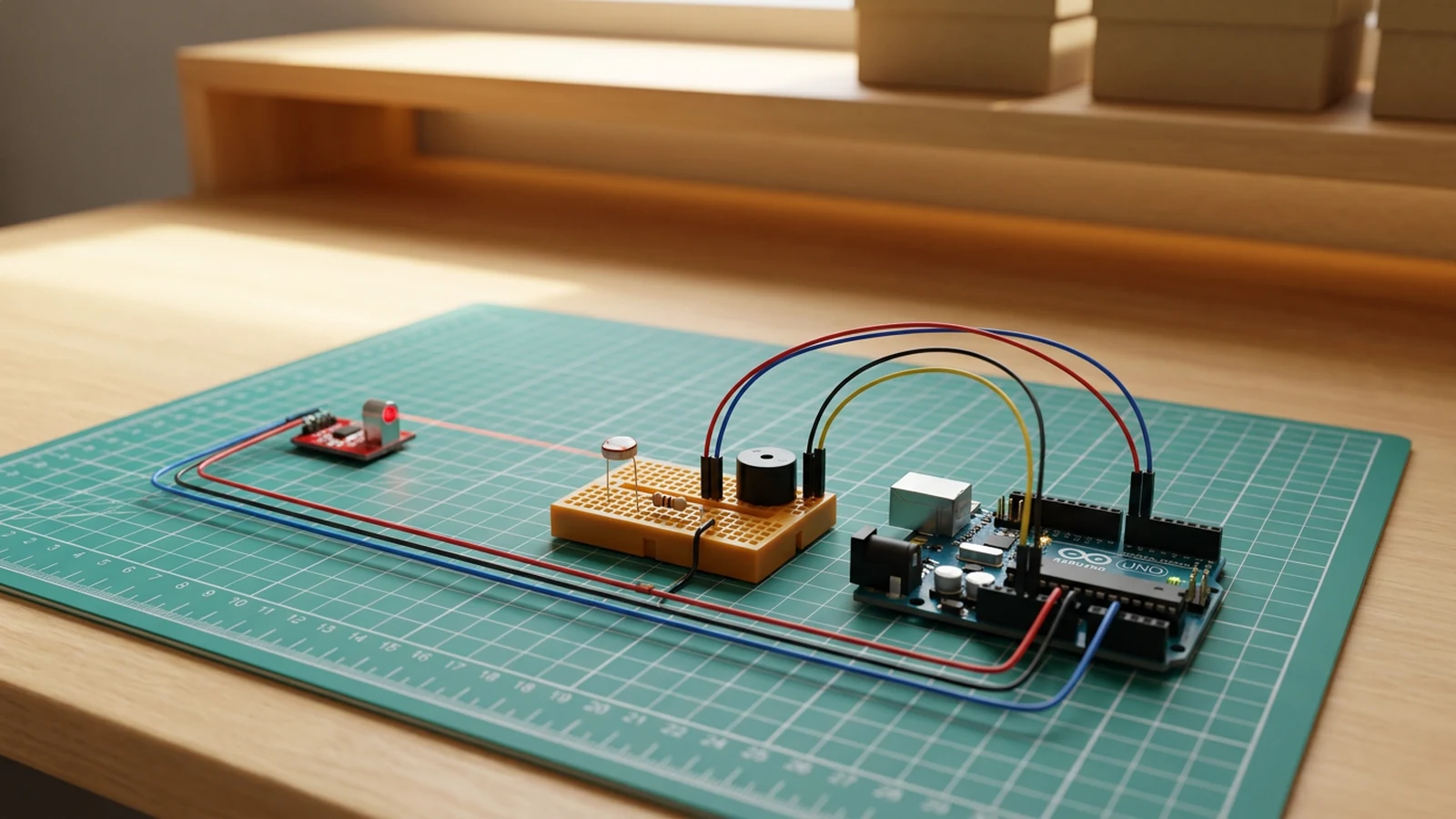
This guide builds a safe laser tripwire alarm demo with an Arduino Uno, a light-dependent resistor, a 10k resistor, a piezo buzzer, and a low-power laser module. The laser shines continuously at the LDR. While the beam is aligned, the Arduino reads a high analogue value and stays quiet. When something blocks the beam, the reading drops below a threshold, the buzzer sounds, and the sketch prints an alert to Serial Monitor.
The project is scoped as a learning build. You will wire a voltage divider for the LDR, read the analogue value on A0, calibrate a threshold from real Serial Monitor readings, and drive the buzzer with tone(). Keeping the laser under firmware control from a digital output means you can turn the beam off in software — useful if you want to add a re-arm delay later.
Safety rule: low-power visible laser only, never aimed at eyes, faces, pets, windows, or reflective surfaces.
What you are building
The firmware has three jobs:
- keep the laser on by holding
LASER_PIN(D2) high, - read the LDR voltage divider on
LDR_PIN(A0) every 100 ms and compare againstLDR_THRESHOLD(default400), - sound the buzzer on
BUZZER_PIN(D5) withtone()at 1 kHz while the beam is broken, and silence it withnoTone()when the beam is restored.
The sketch also prints the raw LDR value to Serial Monitor at 9600 baud on every loop, which makes threshold calibration straightforward. Hysteresis, a status LED, and Bluetooth notification are out of scope for this demo.
Upload and calibrate
Upload the sketch from Schematik and open Serial Monitor at 9600 baud. You will see a continuous stream of LDR values:
Laser tripwire demo ready
LDR value: 820
LDR value: 817
LDR value: 412
LDR value: 38
The first readings should be high (beam hitting the LDR), then drop when you block the beam. Note both values. The constant to adjust is:
const int LDR_THRESHOLD = 400;
Set LDR_THRESHOLD to a value midway between your beam-on and beam-blocked readings. If the buzzer never fires despite a blocked beam, the ambient light is strong enough to keep the LDR reading above the threshold — try shielding the LDR with a short cardboard tube to reduce stray light. If the buzzer fires while the beam is aligned, lower the threshold.
Once calibrated, block the beam with a card and confirm "Intruder detected: beam broken" appears in Serial Monitor.
Troubleshooting
- LDR value stays flat or near zero. The LDR or 10k resistor is not making contact at the A0 node. Check that both legs share the same breadboard row connected to A0, and that the 10k goes from that row to GND, not to 5 V.
- LDR value barely changes when the beam is blocked. Strong ambient light is swamping the laser contribution. Shield the LDR from room lighting with a short tube and retest.
- Buzzer fires continuously even with the beam aligned.
LDR_THRESHOLDis set higher than the beam-on reading. Print the beam-on value and set the threshold well below it. - Buzzer is silent even when the beam is clearly blocked. Confirm the buzzer is passive (not active). An active buzzer with a built-in oscillator will sometimes not respond to
tone(). Also check the SIG pin is on D5 and GND is connected. - Laser does not turn on. Verify D2 drives the transistor base through 1 kΩ, the emitter is at GND, and the module VCC is on 5 V. Check the transistor's pin order against its datasheet because 2N3904 and 2N2222 packages are not always pinned alike.
Going further
This demo shows the core principle cleanly. The two most practical extensions are a re-arm delay and a status LED. A re-arm delay stops the buzzer after a fixed period and waits for the beam to be restored before arming again — this avoids a continuous alarm during a slow crossing. A status LED (green for armed, red for triggered) makes the state visible at a distance without Serial Monitor.
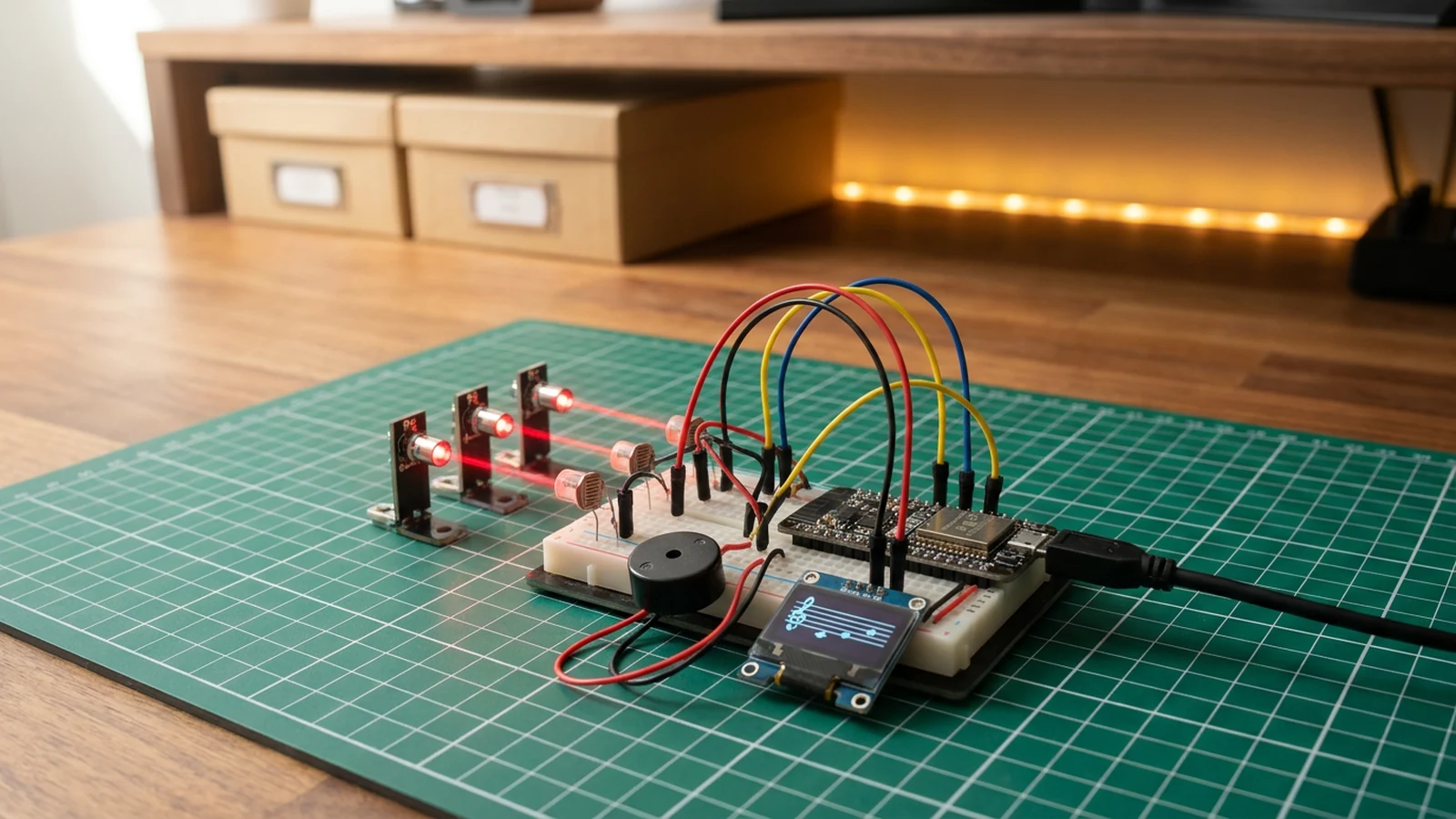
For a multi-beam version with note output instead of a buzzer alarm, the Laser Harp Synth guide uses three LDR channels on an ESP32 with tone-per-channel output, which is a natural next step once this single-channel circuit is solid.
Wiring diagram
Gather all the parts
Assemble it in 3 steps
1. Build the LDR divider
Place the LDR so one leg goes to 5V and the other leg shares a row with A0. Add the 10k resistor from that same A0 row to GND.
- Point the laser at the LDR before powering the circuit.
- Use only a low-power visible laser and never aim it at eyes, pets, reflective surfaces, or people.
2. Wire the transistor-switched laser and buzzer
Connect the laser module positive or VCC lead to 5V and its ground lead to the 2N3904 collector. Connect the transistor emitter to GND and drive its base from D2 through the 1 kΩ resistor. Connect the buzzer signal to D5 and its negative lead to GND.
- Share a common ground across the transistor, buzzer, LDR divider, and Arduino.
- Check the transistor pin order against its datasheet; 2N3904 packages are not all pinned identically.
- This is a toy alarm demo, not a real security or access-control system.
3. Upload and calibrate
Upload the sketch, open Serial Monitor at 9600 baud, and note the LDR readings with the beam hitting and missing the sensor. Adjust LDR_THRESHOLD if your readings sit above or below 400.
- Increase the threshold if the buzzer never fires; decrease it if it fires while the beam is aligned.
Review all connections
1. Connections between "1k-base-resistor" and "Arduino"
2. Connections between "buzzer-1" and "Arduino"
3. Connections between "laser-module-1" and "Arduino"
4. Connections between "laser-security-demo-npn-driver-1" and "Arduino"
5. Connections between "ldr-1" and "Arduino"
6. Connections between "resistor-10k-1" and "Arduino"
Deploy the firmware
#include <Arduino.h>

const int LASER_PIN = 2;
const int BUZZER_PIN = 5;
const int LDR_PIN = A0;
const int LDR_THRESHOLD = 400;

void setup() {
  Serial.begin(9600);
  pinMode(LASER_PIN, OUTPUT);
  pinMode(BUZZER_PIN, OUTPUT);
  pinMode(LDR_PIN, INPUT);
  digitalWrite(LASER_PIN, HIGH);
  noTone(BUZZER_PIN);
  Serial.println("Laser tripwire demo ready");
}

void loop() {
  int lightLevel = analogRead(LDR_PIN);
  Serial.print("LDR value: " );
  Serial.println(lightLevel);

  if (lightLevel < LDR_THRESHOLD) {
    tone(BUZZER_PIN, 1000);
    Serial.println("Intruder detected: beam broken");
  } else {
    noTone(BUZZER_PIN);
  }

  delay(100);
}
Remix this project
Make it yours in one click
Open a full copy of this project in your own Schematik workspace — diagram, code, parts, and assembly steps included. Swap the sensor, add features, or redesign the whole thing with AI. The author's original stays untouched.
Related projects
How to Build a Laser Harp Synth with ESP32
ESP32 · Beginner · 40 minutes · June 12, 2026Schematik
How to Build an Arcade Reaction Tower with ESP32
ESP32 · Beginner · 40 minutes · June 12, 2026Schematik
How to Build an RFID Treasure Chest with ESP32
ESP32 · Intermediate · 50 minutes · June 12, 2026Schematik