Schematik build
How to Build a Cosmic Critter Pet with Raspberry Pi Pico
A tiny alien pet with tilt-based moods, nebula lights, and chirpy sounds
What you'll build
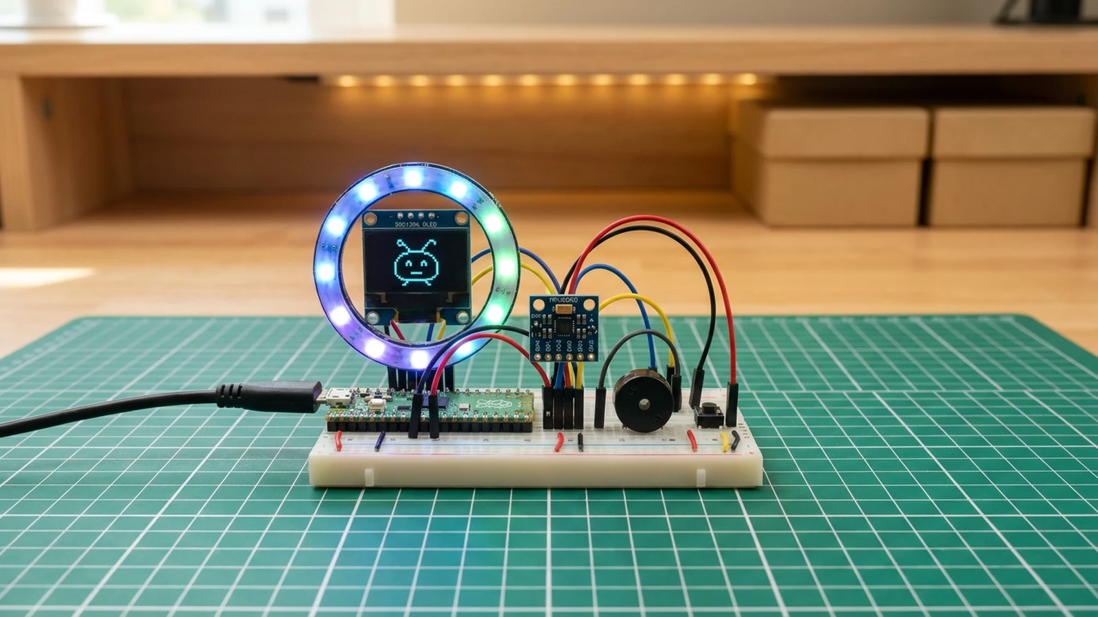
In this guide you will bring a Cosmic Critter to life on a Raspberry Pi Pico using an MPU6050 accelerometer, a 0.96-inch OLED display for its animated face, a WS2812B LED ring for nebula-inspired ambient lighting, and a piezo buzzer for chirps. The critter reads tilt from the accelerometer and maps it to one of four moods — HAPPY, SLEEPY, DIZZY, or HYPER — updating the OLED face, LED ring colour, and buzzer tone accordingly. Tilt it hard along one axis and it goes hyper; tip it the other way and it drifts to sleep; rock it sideways and it gets dizzy. Leave it flat and it stays content. A button lets you cycle moods manually.
The Raspberry Pi Pico is a solid beginner platform for this kind of project. The RP2040 chip handles I2C, PWM, and the PIO-driven WS2812B protocol without needing external timers or interrupts. The firmware uses the Arduino-compatible mbed core, so the libraries feel familiar if you have worked with Arduino before. You will learn how to read accelerometer data over I2C, apply threshold logic to derive discrete states, drive a NeoPixel ring with FastLED, and generate tones on a buzzer using analogWrite-style PWM.
When you finish you will have a self-contained interactive toy that runs from any USB power bank. The code is organised into clear sections for mood logic, LED patterns, face rendering, and sound, so extending it — adding new moods, swapping in a light sensor, changing the chirp melody — is a matter of editing one function at a time. For a button-only take on the virtual pet concept, see the ClawdBot Tamagotchi.
What you are building
This guide covers one complete Cosmic Critter unit. The firmware has four jobs:
- Read acceleration from the MPU6050 over I2C and map the X/Y values to a mood state (HAPPY, SLEEPY, DIZZY, or HYPER).
- Render a matching face on the SSD1306 OLED and update the WS2812B LED ring colour and animation.
- Emit a short chirp on the piezo buzzer every 3 seconds when idle.
- Debounce the mood button and let it cycle through all four moods manually.
This guide does not cover enclosure fabrication, battery management circuits, or multi-unit communication. Those are meaningful extensions but they are not needed to get a working critter.
Upload and calibrate
Flash the firmware via Schematik's one-click upload or copy the .uf2 file to the Pico in BOOTSEL mode. Open Serial Monitor at 115200 baud. On successful boot you should see:
Cosmic Critter ready
If that line does not appear within two seconds of power-on, the MPU6050 initialisation has failed — check GP4/GP5 wiring first.
Pin constants to know. The firmware defines SDA_PIN and SCL_PIN as GP4 and GP5 respectively, but it calls Wire.begin() without arguments. On the RP2040 mbed core, Wire.begin() always uses the variant's fixed I2C pins; a static_assert in the firmware confirms that PIN_WIRE_SDA == 4 and PIN_WIRE_SCL == 5 at compile time. If you try to move I2C to other pins by changing those constants alone, the assert will fail — you would also need to switch to Wire1. For this build, leave them at GP4/GP5.
Other constants. LED_PIN is GP12, BTN_PIN is GP14, BUZZER_PIN is GP15, and NUM_LEDS is 12. FastLED brightness is fixed at 120 out of 255 — enough to see the colours clearly without drawing excessive current. The loop runs on a 50 ms delay.
Tilt thresholds. The firmware reads accelX and accelY in m/s² from the MPU6050 (range set to MPU6050_RANGE_4_G) and applies these rules in order:
accelX > 5.0→ HYPERaccelX < -5.0→ SLEEPYabs(accelY) > 6.0→ DIZZY- else → HAPPY
If your critter flips to HYPER while sitting flat on a table, the MPU6050 axes may be rotated relative to the expected orientation — try reseating the board or rotating it 90 degrees. If all four moods feel too sensitive or too sluggish, adjust the 5.0 and 6.0 thresholds directly in the firmware.
Button behaviour. The button on GP14 cycles through HAPPY → SLEEPY → DIZZY → HYPER → HAPPY with a 250 ms debounce window. Press it to override the tilt logic and test each mood's LED pattern and face before you start tilting the device around.
Chirp timing. The buzzer emits a short chirp every 3000 ms when the critter is in an idle state. If you want less frequent chirps, increase that interval; if you want silence entirely, leave the buzzer unconnected.
Troubleshooting
- Serial Monitor shows nothing after power-on. Confirm baud rate is 115200. If still nothing, the firmware is likely stalling at
mpu.begin()— check that GP4 and GP5 are correctly connected to the MPU6050 SDA and SCL pins. - OLED stays blank but MPU6050 works. The SSD1306 and MPU6050 share the I2C bus. If the OLED is blank, it is likely at a different I2C address than 0x3C, or its SDA/SCL leads are swapped. Some SSD1306 breakouts have SDA and SCL in a different order than the MPU6050 — compare the two silkscreens carefully.
- I2C wired to GP2/GP3 instead of GP4/GP5. The mbed core's
Wire.begin()is hard-wired to the variant's GP4/GP5 regardless of whatSDA_PINandSCL_PINconstants say. Moving the physical wires to GP2/GP3 will break I2C silently. Keep all I2C peripherals on GP4/GP5. - LED ring flickers or Pico resets when LEDs first light up. The WS2812B ring draws a surge of current on startup. Fit the 470 µF capacitor across VBUS and GND as close to the ring's power pads as possible. If flicker persists, check that the ring's GND is tied to Pico GND, not floating.
- Mood never changes with tilt. Open Serial Monitor and watch for mood state output. If the state is always HAPPY regardless of tilt, either the MPU6050 is reading near-zero (flat orientation or a wiring fault) or the thresholds are too high for your mount angle. Try tilting the Pico sharply past 45 degrees; if it still stays HAPPY, print
accelXandaccelYraw values to confirm the sensor is producing real data. - Button mood cycle does not respond. INPUT_PULLUP means the button should connect GP14 to GND when pressed, not to 3V3. If you wired it to 3V3, the pin will never read LOW and the button will appear dead.
Going further
The four mood states are defined in a single switch block. Adding a fifth mood — say, ANGRY triggered by a sudden sharp tap — means adding one threshold check and one case with its own LED colour, face bitmap, and buzzer pitch. The MPU6050 also exposes a gyroscope; you could use rotation rate instead of (or alongside) tilt to distinguish a slow tip from a sudden shake.
For a wearable version, swap the breadboard for a small perfboard, replace jumper wires with short solid-core wire, and power everything from a 3.7 V LiPo through a Pico LiPo board that handles charging over USB. The firmware requires no changes — the mbed core abstracts the voltage supply — though you will want to lower FastLED.setBrightness from 120 to something lower to extend battery life.
Wiring diagram
Gather all the parts
Assemble it in 4 steps
1. Connect I2C sensors to the Pico
Wire MPU6050 and SSD1306 OLED: VCC to 3.3V, GND to ground, SDA to GP4, SCL to GP5. Both share the same I2C bus.
- Keep I2C wires short and double-check that all modules share GND.
- Pico GPIO is 3.3V only — do not connect 5V logic to any GPIO pin.
2. Build the buffered 5 V LED path
Plug the 5 V USB-C supply into the socket breakout. Connect VBUS/5V to the LED 5V pin and 74AHCT125 VCC; share breakout, MCU, LED, and buffer grounds. Connect MCU GPIO12 to 1A, tie 1OE to GND, then connect 1Y through the 220 Ω resistor to DIN. Place the bulk capacitor across LED 5V and GND with correct polarity. Tie unused inputs 2A, 3A, and 4A to GND and unused enables 2OE, 3OE, and 4OE to 5 V.
- Place the resistor and capacitor close to the first LED.
- Unplug power while wiring and verify the breakout output is 5 V with correct polarity before connecting electronics.
- Do not connect the MCU GPIO directly to DIN.
3. Add buzzer and mood button
Connect piezo buzzer signal to GP15 (other lead to GND). Wire mood button between GP14 and GND — the code enables the internal pull-up.
- A 100 Ω resistor in series with the buzzer can reduce volume if needed.
4. Upload and play
Flash the sketch via USB. Tilt the Pico to change the critter mood — level for happy, forward tilt for sleepy, sideways for dizzy, backward for hyper. Press the button to manually cycle moods.
- Experiment with the tilt thresholds in the code to match your preferred sensitivity.
Review all connections
1. Connections between "pico-buzzer-1" and "Raspberry Pi Pico"
2. Connections between "pico-cosmic-critter-bulk-capacitor-1" and "Raspberry Pi Pico"
3. Connections between "pico-cosmic-critter-led-data-resistor-1" and "Raspberry Pi Pico"
4. Connections between "pico-cosmic-critter-logic-level-shifter-1" and "Raspberry Pi Pico"
5. Connections between "pico-cosmic-critter-regulated-5v-supply-1" and "Raspberry Pi Pico"
6. Connections between "pico-cosmic-critter-usb-c-power-breakout-1" and "Raspberry Pi Pico"
7. Connections between "pico-imu-1" and "Raspberry Pi Pico"
8. Connections between "pico-led-ring-1" and "Raspberry Pi Pico"
9. Connections between "pico-mode-button-1" and "Raspberry Pi Pico"
10. Connections between "pico-oled-1" and "Raspberry Pi Pico"
Deploy the firmware
#include <Wire.h>
#include <FastLED.h>
#include <Adafruit_MPU6050.h>
#include <Adafruit_SSD1306.h>

#define SDA_PIN 4
#define SCL_PIN 5
#define BTN_PIN 14
#define BUZZER_PIN 15
#define LED_PIN 12
#define NUM_LEDS 12

Adafruit_MPU6050 mpu;
Adafruit_SSD1306 display(128, 64, &Wire, -1);
CRGB leds[NUM_LEDS];

enum Mood { HAPPY, SLEEPY, DIZZY, HYPER };
Mood mood = HAPPY;
Mood prevMood = HAPPY;
unsigned long lastChirpMs = 0;
unsigned long lastBtnMs = 0;

const char* moodName(Mood m) {
  switch (m) {
    case HAPPY:  return "Happy  :)";
    case SLEEPY: return "Sleepy zzz";
    case DIZZY:  return "Dizzy  @_@";
    case HYPER:  return "Hyper  !!!";
    default:     return "Unknown";
  }
}

void renderMoodLights(Mood m) {
  switch (m) {
    case HAPPY:
      fill_solid(leds, NUM_LEDS, CRGB(0, 120, 255));
      break;
    case SLEEPY:
      for (int i = 0; i < NUM_LEDS; i++) {
        uint8_t v = beatsin8(12, 30, 100, 0, i * 20);
        leds[i] = CRGB(v / 2, 0, v);
      }
      break;
    case DIZZY:
      for (int i = 0; i < NUM_LEDS; i++) {
        leds[i] = CHSV((millis() / 10 + i * 21) % 255, 255, 140);
      }
      break;
    case HYPER:
      for (int i = 0; i < NUM_LEDS; i++) {
        leds[i] = ((millis() / 80 + i) % 2 == 0) ? CRGB::OrangeRed : CRGB::Gold;
      }
      break;
  }
  FastLED.show();
}

void chirp(Mood m) {
  switch (m) {
    case HAPPY:  tone(BUZZER_PIN, 1400, 70); break;
    case SLEEPY: tone(BUZZER_PIN, 750, 120); break;
    case DIZZY:  tone(BUZZER_PIN, 1800, 40); break;
    case HYPER:  tone(BUZZER_PIN, 2200, 50); break;
  }
}

void setup() {
  Serial.begin(115200);
  // RP2040 mbed core: Wire uses the variant's fixed I2C pins. The
  // static_asserts prove at build time that those are GP4/GP5, matching
  // the wiring table.
  static_assert(PIN_WIRE_SDA == SDA_PIN, "Pico variant SDA is not GP4");
  static_assert(PIN_WIRE_SCL == SCL_PIN, "Pico variant SCL is not GP5");
  Wire.begin();

  if (!mpu.begin()) Serial.println("MPU6050 not found");
  mpu.setAccelerometerRange(MPU6050_RANGE_4_G);

  display.begin(SSD1306_SWITCHCAPVCC, 0x3C);
  display.setTextSize(1);
  display.setTextColor(SSD1306_WHITE);

  FastLED.addLeds<NEOPIXEL, LED_PIN>(leds, NUM_LEDS);
  FastLED.setBrightness(120);

  pinMode(BTN_PIN, INPUT_PULLUP);
  pinMode(BUZZER_PIN, OUTPUT);
  Serial.println("Cosmic Critter ready");
}

void loop() {
  sensors_event_t a, g, t;
  mpu.getEvent(&a, &g, &t);

  if (a.acceleration.x > 5.0f)      mood = HYPER;
  else if (a.acceleration.x < -5.0f) mood = SLEEPY;
  else if (fabs(a.acceleration.y) > 6.0f) mood = DIZZY;
  else mood = HAPPY;

  if (!digitalRead(BTN_PIN) && millis() - lastBtnMs > 250) {
    mood = static_cast<Mood>((mood + 1) % 4);
    chirp(mood);
    lastBtnMs = millis();
  }

  if (mood != prevMood) {
    chirp(mood);
    prevMood = mood;
  }

  if (millis() - lastChirpMs > 3000) {
    chirp(mood);
    lastChirpMs = millis();
  }

  renderMoodLights(mood);

  display.clearDisplay();
  display.setCursor(0, 0);
  display.println("Pico Cosmic Critter");
  display.println("--------------------");
  display.print("Mood: ");
  display.println(moodName(mood));
  display.println();
  char tiltLine[20];
  snprintf(tiltLine, sizeof(tiltLine), "Tilt X: %5.1f", a.acceleration.x);
  display.println(tiltLine);
  snprintf(tiltLine, sizeof(tiltLine), "Tilt Y: %5.1f", a.acceleration.y);
  display.println(tiltLine);
  display.println("BTN: cycle mood");
  display.display();

  delay(50);
}
Remix this project
Make it yours in one click
Open a full copy of this project in your own Schematik workspace — diagram, code, parts, and assembly steps included. Swap the sensor, add features, or redesign the whole thing with AI. The author's original stays untouched.
Related projects
How to Build a ClawdBot Tamagotchi with ESP32
ESP32 · Beginner · 45 minutes · July 22, 2026Schematik
How to Build an Arcade Reaction Tower with ESP32
ESP32 · Beginner · 40 minutes · June 12, 2026Schematik
How to Build a Plant Disco Guardian with ESP32
ESP32 · Beginner · 35 minutes · July 22, 2026Schematik