Schematik build
How to Build a ClawdBot Tamagotchi with ESP32
A lobster-bot companion with moods, needs, and personality loops
What you'll build
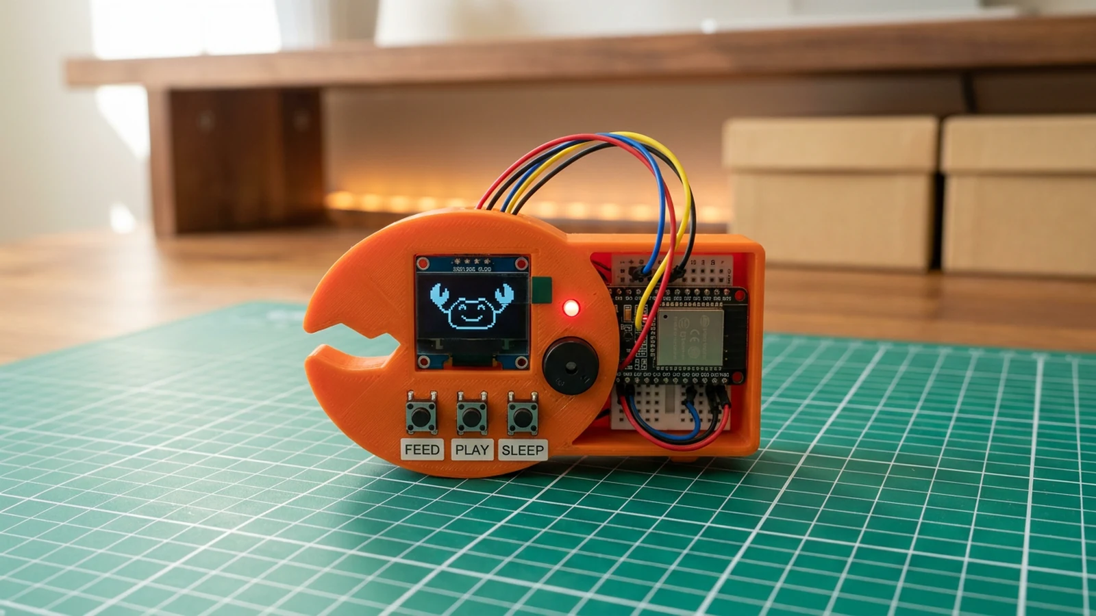
This project guides you through creating ClawdBot, a Tamagotchi-inspired lobster companion that lives on an ESP32 with an OLED screen, three tactile buttons, and a piezo buzzer. ClawdBot has three core needs — hunger, entertainment, and energy — that decay over time. Press the Feed button to top up hunger with a satisfying crunch sound, the Play button to boost entertainment with a cheerful jingle, or the Sleep button to let ClawdBot recharge with a snoring animation and soft pulsing tone. Neglect any need for too long and ClawdBot's expressive OLED face shifts from happy to grumpy to downright furious, complete with claw-snapping animations and an annoyed buzz.
What makes this project a good learning experience is the care loop at its core. You will implement a time-based state machine that ticks down each need independently, transitions between mood states using threshold checks, and triggers different face animations and sound effects depending on ClawdBot's overall care score. This teaches event-driven programming, debounced button handling, non-blocking timers with millis(), and how to manage multiple concurrent state variables — all patterns that apply to every embedded system you build after this one.
The finished ClawdBot is a charming desk companion that demands just enough attention to stay engaging without becoming annoying. The code is structured so you can easily add new needs, introduce personality traits, or add a growth system where consistent care unlocks new animations and sounds. If you enjoyed this build, the Cosmic Critter Pico project makes an excellent follow-up that explores motion-based interaction on a different platform.
What you are building
This guide covers a single ClawdBot unit with a care loop and five mood states. The firmware has four jobs:
- Track how long since the last interaction and move through mood states at the 30 s, 60 s, and 90 s thresholds.
- Read three debounced buttons and update the care score accordingly.
- Drive the OLED face with a matching expression and drive the piezo buzzer with a matching sound.
- Blink the status LED at a rate that reflects the current mood.
This guide does not cover multiplayer proximity features, persistent save data across power cycles, or wireless connectivity. Get the care loop working reliably on one device first.
Upload and calibrate
Install the Adafruit SSD1306 and Adafruit GFX Library libraries via the Arduino Library Manager, then flash the sketch from Schematik.
Open Serial Monitor at 115200 baud. On successful boot you will see:
ClawdBot ready
If you see nothing, confirm the baud rate and that the board is not stuck in a boot loop due to a wiring short.
Key constants to know before you start tweaking:
BTN_FEED(GPIO 32),BTN_PLAY(GPIO 33),BTN_SLEEP(GPIO 25) — button pin assignments. If a button press triggers the wrong action, swap the corresponding#define.BUZZER_PIN(GPIO 26) — the pin used withtone(). If you are using an active buzzer instead of a passive one, the tonal melodies will not work correctly; swap for a passive buzzer.STATUS_LED(GPIO 27) — the indicator LED. Solid HIGH means ClawdBot is happy. Fast blink at 180 ms means cranky. Slow blink at 800 ms means sleepy.- Idle thresholds: 30 s moves ClawdBot to HUNGRY, 60 s to BORED, 90 s to CRANKY. Once cranky, the care score decreases by 1 point per second until you intervene.
Care score changes per interaction: Feed adds 30 points, Play adds 20, Sleep adds 15. The score is capped at 100 and starts there. Watch the Serial Monitor while pressing buttons — the sketch logs mood transitions so you can confirm each threshold is triggering at the right time.
Troubleshooting
- OLED stays blank after power-on. Confirm SDA is on GPIO 21 and SCL on GPIO 22, that VCC is on 3V3 not 5 V, and that the I2C address is 0x3C. Run an I2C scanner sketch if the address is in question — some batches ship at 0x3D.
- Button press has no effect or double-fires. The firmware uses a 200 ms debounce window. If presses are being ignored, check that the button leg is wired to GND, not floating. If a single press triggers two actions, the debounce delay may need to be increased slightly in the sketch.
- ClawdBot goes cranky faster than expected. The 30 s / 60 s / 90 s thresholds are measured from the last button press, not from boot. If the idle timer appears to reset unexpectedly, check that
millis()overflow is not affecting your modified copy — the sketch handles wrap-around but custom changes can break that. - Buzzer produces no sound. Confirm GPIO 26 is connected to the SIG pin of a passive piezo buzzer, not an active one. Also confirm
tone()is supported on your ESP32 core version; some older board packages have incompletetone()support. - Status LED is always off or always on. Check the resistor is in series, not bypassed. Confirm the LED polarity — the longer leg (anode) goes toward GPIO 27. If the LED is correct and the pin is
STATUS_LED(GPIO 27), re-flash to rule out an incomplete upload. - Care score drops too quickly. The repaired firmware decrements it once per second in CRANKY state. If it falls faster, check that your sketch includes the
lastDecayMsguard rather than subtracting on every loop pass.
Going further
Once the core care loop is stable, the most meaningful extension is persistent storage. The ESP32's NVS (non-volatile storage) lets you save the care score and mood state across power cycles so ClawdBot picks up where it left off rather than resetting to full health on every boot. The Preferences library wraps NVS with a simple key-value interface and requires only a handful of lines at startup and shutdown.
A second useful direction is physical personality. Swapping out face bitmaps for a set that varies slightly between units — slightly different eye spacing, a different claw shape — makes each ClawdBot feel distinct. Combine that with a seed value stored in NVS and every device can have a procedurally assigned appearance that persists for its lifetime.
Wiring diagram
Gather all the parts
Assemble it in 4 steps
1. Wire the OLED face display
Connect OLED VCC to 3.3V, GND to ground, SDA to GPIO21, and SCL to GPIO22.
- Confirm the I2C address — most modules use 0x3C.
2. Add the three care buttons
Wire Feed button between GPIO32 and GND, Play button between GPIO33 and GND, and Sleep button between GPIO25 and GND. Internal pull-ups are enabled in code.
- Color-code the buttons (green=feed, blue=play, purple=sleep) for easier identification.
3. Connect buzzer and status LED
Wire piezo buzzer signal to GPIO26 (other lead to GND). Connect status LED anode to GPIO27 through a 220 Ω resistor, cathode to GND.
- The LED blinks fast when cranky, slow when sleepy, and stays solid when happy.
4. Upload and interact
Flash the sketch. ClawdBot starts happy — if you ignore it for 30 seconds it gets hungry, then bored, then cranky. Press the buttons to keep it happy and maintain the care score.
- Adjust the idle thresholds in code to make ClawdBot needier or more independent.
Review all connections
1. Connections between "clawdbot-buzzer-1" and "ESP32"
2. Connections between "clawdbot-led-1" and "ESP32"
3. Connections between "clawdbot-oled-1" and "ESP32"
4. Connections between "clawdbot-tamagotchi-220-ohm-resistor-1" and "ESP32"
5. Connections between "feed-button-1" and "ESP32"
6. Connections between "play-button-1" and "ESP32"
7. Connections between "sleep-button-1" and "ESP32"
Deploy the firmware
#include <Wire.h>
#include <Adafruit_GFX.h>
#include <Adafruit_SSD1306.h>

#define SDA_PIN 21
#define SCL_PIN 22
#define BTN_FEED 32
#define BTN_PLAY 33
#define BTN_SLEEP 25
#define BUZZER_PIN 26
#define STATUS_LED 27

Adafruit_SSD1306 display(128, 64, &Wire, -1);

enum Mood { HAPPY, HUNGRY, SLEEPY, BORED, CRANKY };
Mood mood = HAPPY;
unsigned long lastCareMs = 0;
unsigned long lastBtnMs = 0;
unsigned long lastDecayMs = 0;
int careScore = 100;

const char* moodName(Mood m) {
  switch (m) {
    case HAPPY:  return "Happy  ^_^";
    case HUNGRY: return "Hungry >_<";
    case SLEEPY: return "Sleepy -_-";
    case BORED:  return "Bored  ._.";
    case CRANKY: return "Cranky !!!";
    default:     return "Unknown";
  }
}

void playTone(int freq, int dur) {
  tone(BUZZER_PIN, freq, dur);
  delay(dur + 10);
  noTone(BUZZER_PIN);
}

void feedAction() {
  playTone(1760, 60);
  playTone(2100, 60);
  mood = HAPPY;
  careScore = min(100, careScore + 30);
  lastCareMs = millis();
}

void playAction() {
  playTone(1480, 50);
  playTone(1760, 50);
  playTone(2200, 60);
  mood = HAPPY;
  careScore = min(100, careScore + 20);
  lastCareMs = millis();
}

void sleepAction() {
  playTone(980, 90);
  playTone(780, 120);
  mood = SLEEPY;
  careScore = min(100, careScore + 15);
  lastCareMs = millis();
}

void setup() {
  Serial.begin(115200);
  delay(100);

  Wire.begin(SDA_PIN, SCL_PIN);
  display.begin(SSD1306_SWITCHCAPVCC, 0x3C);
  display.setTextSize(1);
  display.setTextColor(SSD1306_WHITE);

  pinMode(BTN_FEED, INPUT_PULLUP);
  pinMode(BTN_PLAY, INPUT_PULLUP);
  pinMode(BTN_SLEEP, INPUT_PULLUP);
  pinMode(BUZZER_PIN, OUTPUT);
  pinMode(STATUS_LED, OUTPUT);
  digitalWrite(STATUS_LED, HIGH);

  lastCareMs = millis();
  Serial.println("ClawdBot ready");
}

void loop() {
  unsigned long idleMs = millis() - lastCareMs;
  unsigned long now = millis();

  if (idleMs > 90000) {
    mood = CRANKY;
    if (now - lastDecayMs >= 1000) {
      careScore = max(0, careScore - 1);
      lastDecayMs = now;
    }
  }
  else if (idleMs > 60000) mood = BORED;
  else if (idleMs > 30000) mood = HUNGRY;

  if (now - lastBtnMs > 200) {
    if (!digitalRead(BTN_FEED))  { feedAction();  lastBtnMs = now; }
    if (!digitalRead(BTN_PLAY))  { playAction();  lastBtnMs = now; }
    if (!digitalRead(BTN_SLEEP)) { sleepAction(); lastBtnMs = now; }
  }

  display.clearDisplay();
  display.setCursor(0, 0);
  display.println("  ClawdBot Tamagochi");
  display.println("--------------------");
  display.print("Mood:  ");
  display.println(moodName(mood));
  display.printf("Care:  %d%%\n", careScore);
  display.printf("Idle:  %lus\n", idleMs / 1000);
  display.println();
  display.println("Feed / Play / Sleep");
  display.display();

  if (mood == CRANKY) {
    digitalWrite(STATUS_LED, (millis() / 180) % 2);
  } else if (mood == SLEEPY) {
    digitalWrite(STATUS_LED, (millis() / 800) % 2);
  } else {
    digitalWrite(STATUS_LED, HIGH);
  }

  delay(30);
}
Remix this project
Make it yours in one click
Open a full copy of this project in your own Schematik workspace — diagram, code, parts, and assembly steps included. Swap the sensor, add features, or redesign the whole thing with AI. The author's original stays untouched.
Related projects
How to Build a Cosmic Critter Pet with Raspberry Pi Pico
Raspberry Pi Pico · Beginner · 40 minutes · July 22, 2026Schematik
How to Build a Gesture-Controlled Mood Lamp with ESP32
ESP32 · Beginner · 45 minutes · July 22, 2026Schematik
How to Build an Arcade Reaction Tower with ESP32
ESP32 · Beginner · 40 minutes · June 12, 2026Schematik