Schematik build
How to Build an ESP32 Air Quality Monitor with BME280
Live temperature, humidity, and pressure readings with a comfort label on OLED
What you'll build
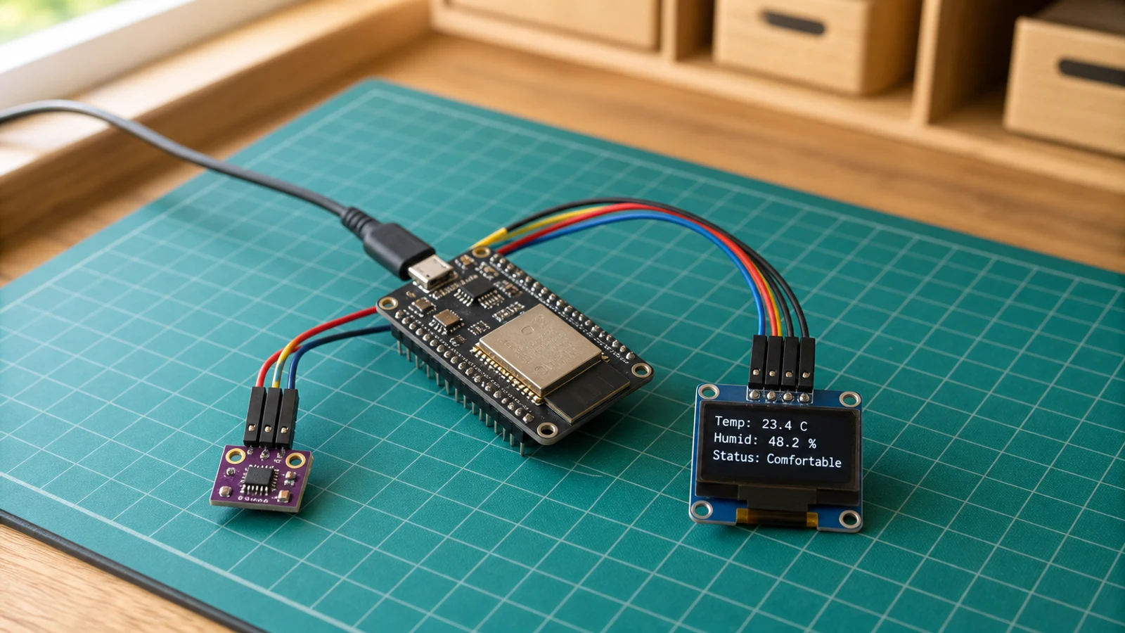
This guide walks you through building an indoor air quality monitor with an ESP32, a BME280 sensor, and a compact SSD1306 OLED display. The BME280 reads the room environment every two seconds and the OLED shows live temperature in degrees Celsius, relative humidity as a percentage, barometric pressure in hectopascals, and a plain-language comfort label — Cold, Hot, Humid, Dry, or Comfortable. Both the sensor and the display share the same I2C bus, so only four signal wires connect the entire circuit to the ESP32.
You will learn how to initialise the BME280 over I2C, configure oversampling and filtering for stable indoor readings, and share the bus between two peripherals at different addresses. The project also shows how to draw formatted multi-line output on a 128×64 OLED and structure a non-blocking sensor loop that keeps the display responsive without tying up the main loop with delays.
When you are finished you will have a desk-sized environment monitor that updates in real time and is useful from the moment you power it on. The code is straightforward to extend: add Wi-Fi to push readings to a dashboard, wire in an RGB LED that changes colour with the comfort label, or log data to an SD card for overnight trends. If you already built the weather station, this project is a natural companion — one shows what the forecast says outside, the other shows what conditions are like right now in the room.
What you are building
Precise scope for this guide:
- Wire a BME280 Sensor and SSD1306 OLED to an ESP32 over a shared I2C bus.
- Read temperature, humidity, and pressure from the BME280 every two seconds.
- Derive a single-word comfort label from those readings using the
comfortLabelfunction. - Display all four values on the OLED in a clear, multi-line layout.
- Print the same readings to the Serial Monitor at 115200 baud for easy debugging.
Out of scope: Wi-Fi connectivity, cloud logging, historical graphing, alerts, or any persistent storage.
Upload and calibrate
Install the following libraries via the Arduino IDE Library Manager (Sketch → Include Library → Manage Libraries) before compiling:
- Adafruit SSD1306
- Adafruit GFX Library
- Adafruit BME280 Library
- Adafruit Unified Sensor
Open the sketch, select your ESP32 board under Tools → Board, and choose the correct port. The sketch defines these constants near the top:
OLED_SDA— set to21OLED_SCL— set to22READ_INTERVAL_MS— set to2000(milliseconds between sensor reads)
You should not need to change any of these for a standard ESP32 dev board. If your BME280 breakout has SDO pulled high, open the sketch and change the BME280 initialisation address from 0x76 to 0x77.
Click Upload. Once flashing completes, open the Serial Monitor (Tools → Serial Monitor) and set the baud rate to 115200. You should see a line printed roughly every two seconds in this form:
Temp: 22.4 C Humidity: 48.2 % Pressure: 1013.1 hPa [Comfortable]
The OLED will simultaneously display the same four values across four lines. If the OLED shows nothing, confirm the I2C address is 0x3C — a small number of SSD1306 modules ship set to 0x3D and will need the address changed in the sketch.
The comfortLabel function maps sensor readings to one of five states: Cold, Hot, Humid, Dry, or Comfortable. The thresholds are defined in the sketch and are easy to adjust for your own comfort preferences.
Troubleshooting
-
OLED stays blank after flashing. The I2C address does not match. Run an I2C scanner sketch and confirm whether the display responds at 0x3C or 0x3D, then update the constant in the sketch accordingly.
-
Serial Monitor shows
BME280 init failed. The sensor is not being detected on I2C. Check your SDA and SCL wiring, confirm the sensor is powered from 3V3 (not 5 V), and verify the I2C address is 0x76. If the SDO pin on your breakout is tied high, change the address to 0x77. -
Readings are wildly wrong or frozen. A loose wire on the shared I2C bus will corrupt communication to both devices. Re-seat every jumper, particularly on the breadboard rows shared between the OLED and the BME280.
-
Comfort label never changes from "Comfortable". The
comfortLabelthresholds in the sketch may need adjustment for your local climate. Open the function definition and widen or narrow the temperature and humidity ranges to match your environment. -
Pressure reads 0 or NaN. This usually means the BME280 failed to initialise but the sketch did not halt. Check the Serial Monitor for the
BME280 init failedmessage on startup and address the I2C issue first. -
Upload fails with "no port found". The ESP32 USB-to-serial driver is not installed. Install the CP210x or CH340 driver for your operating system and replug the board.
Going further
The most natural next step is adding Wi-Fi. The ESP32's built-in wireless stack lets you post readings to any HTTP endpoint with about twenty additional lines of code — useful for logging to a home automation system or visualising trends over time. Pair this with a simple time-series store and you can chart how your office temperature tracks across the day.
You can also make the comfort state more visible without any extra dependencies. The ESP32 has enough spare GPIO pins to drive an RGB LED: map Cold to blue, Hot to red, Humid to cyan, Dry to yellow, and Comfortable to green. The result is a monitor you can read at a glance from across the room, even when the OLED text is too small to see.
Wiring diagram
Gather all the parts
Assemble it in 3 steps
1. Wire the I2C bus
Connect the BME280 and OLED to the ESP32 shared I2C bus. Both sensors use the same SDA (GPIO 21) and SCL (GPIO 22) lines.
- Both the BME280 and OLED share the same I2C bus. The BME280 defaults to address 0x76, and the OLED to 0x3C, so they will not conflict.
- If your BME280 board has a different address, try 0x77 in the code.
- Double-check that VCC on both modules goes to 3.3V, not 5V, unless the breakout board has its own regulator.
2. Mount the sensing stack
Mount the BME280 where room air can circulate around it and keep it away from the ESP32 regulator and display back, which can warm the reading. Secure the OLED where it is readable without covering the sensor vent.
- Leave several centimetres between the sensor and heat-producing boards.
- Do not seal the BME280 inside an unventilated enclosure.
3. Flash and verify
Upload the sketch and open Serial Monitor at 115200 baud. You should see temperature, humidity, and pressure readings every two seconds. The OLED will show the values and a comfort label.
- Breathe gently on the BME280 to see humidity and temperature respond in real time.
- The comfort label updates automatically based on simple thresholds you can adjust in the code.
Review all connections
1. Connections between "aqm-bme280-1" and "ESP32"
2. Connections between "aqm-oled-1" and "ESP32"
Deploy the firmware
#include <Wire.h>
#include <Adafruit_GFX.h>
#include <Adafruit_SSD1306.h>
#include <Adafruit_BME280.h>

#define OLED_SDA 21
#define OLED_SCL 22
#define OLED_RESET -1
#define SCREEN_WIDTH 128
#define SCREEN_HEIGHT 64

Adafruit_SSD1306 display(SCREEN_WIDTH, SCREEN_HEIGHT, &Wire, OLED_RESET);
Adafruit_BME280 bme;

unsigned long lastReadMs = 0;
const unsigned long READ_INTERVAL_MS = 2000;

float temperature = 0;
float humidity = 0;
float pressure = 0;

String comfortLabel(float temp, float hum) {
  if (temp < 18) return "Cold";
  if (temp > 28) return "Hot";
  if (hum > 70) return "Humid";
  if (hum < 30) return "Dry";
  return "Comfortable";
}

void drawScreen() {
  display.clearDisplay();
  display.setTextColor(SSD1306_WHITE);

  display.setTextSize(1);
  display.setCursor(0, 0);
  display.println("Air Quality Monitor");
  display.drawLine(0, 10, SCREEN_WIDTH, 10, SSD1306_WHITE);

  display.setCursor(0, 14);
  display.print("Temp:  ");
  display.print(temperature, 1);
  display.println(" C");

  display.setCursor(0, 26);
  display.print("Humid: ");
  display.print(humidity, 1);
  display.println(" %");

  display.setCursor(0, 38);
  display.print("Press: ");
  display.print(pressure, 0);
  display.println(" hPa");

  display.drawLine(0, 50, SCREEN_WIDTH, 50, SSD1306_WHITE);
  display.setCursor(0, 54);
  display.print("Status: ");
  display.println(comfortLabel(temperature, humidity));

  display.display();
}

void setup() {
  Serial.begin(115200);
  delay(100);

  Wire.begin(OLED_SDA, OLED_SCL);

  if (!display.begin(SSD1306_SWITCHCAPVCC, 0x3C)) {
    Serial.println("OLED init failed");
    while (true) delay(1000);
  }

  if (!bme.begin(0x76)) {
    Serial.println("BME280 not found at 0x76, trying 0x77");
    if (!bme.begin(0x77)) {
      Serial.println("BME280 init failed");
      display.clearDisplay();
      display.setTextSize(1);
      display.setTextColor(SSD1306_WHITE);
      display.setCursor(0, 0);
      display.println("BME280 not found!");
      display.println("Check wiring.");
      display.display();
      while (true) delay(1000);
    }
  }

  bme.setSampling(Adafruit_BME280::MODE_NORMAL,
    Adafruit_BME280::SAMPLING_X2,
    Adafruit_BME280::SAMPLING_X16,
    Adafruit_BME280::SAMPLING_X1,
    Adafruit_BME280::FILTER_X16,
    Adafruit_BME280::STANDBY_MS_500);

  Serial.println("Air Quality Monitor ready");
}

void loop() {
  if (millis() - lastReadMs >= READ_INTERVAL_MS) {
    temperature = bme.readTemperature();
    humidity = bme.readHumidity();
    pressure = bme.readPressure() / 100.0;
    lastReadMs = millis();

    Serial.print("T: ");
    Serial.print(temperature, 1);
    Serial.print(" C  H: ");
    Serial.print(humidity, 1);
    Serial.print(" %  P: ");
    Serial.print(pressure, 0);
    Serial.println(" hPa");
  }

  drawScreen();
  delay(100);
}
Remix this project
Make it yours in one click
Open a full copy of this project in your own Schematik workspace — diagram, code, parts, and assembly steps included. Swap the sensor, add features, or redesign the whole thing with AI. The author's original stays untouched.
Related projects
How to Build a Gesture-Controlled Mood Lamp with ESP32
ESP32 · Beginner · 45 minutes · July 22, 2026Schematik
How to Build an ESP32 Weather Station with Clothing Advice
ESP32 · Intermediate · 30 minutes · June 12, 2026Schematik
How to Build a Plant Disco Guardian with ESP32
ESP32 · Beginner · 35 minutes · July 22, 2026Schematik