Schematik build
How to Build an ESP32 Kids Phone Prototype
A kid-safe mini phone with big buttons, approved contacts, and SOS mode
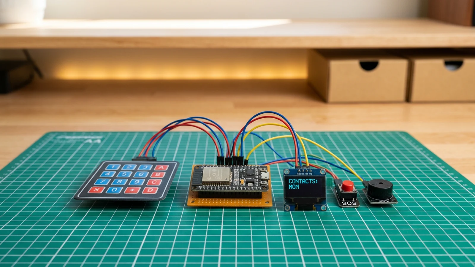
What you'll build
Build a proof-of-concept kids phone using an ESP32, a 4×4 membrane keypad, an SSD1306 OLED display, a piezo speaker, and a dedicated SOS button. The phone stores a short list of approved contacts in the firmware. The child scrolls through them with the A and D keys, confirms a selection with B, and triggers an emergency alert by holding the SOS button for two seconds. When SOS fires, the display flashes a large alert message and the speaker plays a repeating alarm tone.
The interface is intentionally limited. Large text on the OLED, a flat key map, and a minimum number of menu states mean a young child can navigate it reliably. The approved contacts list is edited directly in the firmware before flashing — there is no runtime settings menu.
The firmware has four jobs: scan the 4×4 keypad matrix and map key presses to navigation and call actions; render the contact list and call state on the SSD1306 OLED with large fonts; produce call-confirmation and SOS alarm tones through the piezo speaker; and detect a two-second SOS button hold via a millis() timer and trigger the alert routine. Actual cellular calling requires a GSM module such as the SIM800L and is deliberately outside the scope of this starter.
Upload and calibrate
Open the sketch in Schematik. Edit the approvedContacts array near the top to set the names shown on the display — up to three contacts are stored by default. Flash via USB at 115200 baud and open Serial Monitor at 115200 to confirm boot.
Press A to scroll down the contact list and D to scroll up. Press B to confirm a call (the prototype plays a confirmation tone). Hold the SOS button for two seconds — the OLED should display !! SOS !! in large text and the speaker plays a repeating alarm. Releasing the button clears the alert.
Troubleshooting
- No keys register. Verify the row and column pin order against your specific keypad model. The firmware maps rows to GPIO 14/27/12/13 and columns to GPIO 23/18/17/19. A single swapped wire can shift the entire key map.
- OLED stays blank. Confirm SDA is on GPIO 4 and SCL on GPIO 15 (these are non-default I2C pins). If wiring is correct but the display is still blank, check whether your module uses 0x3D instead of 0x3C.
- SOS never triggers. Check that the button shorts GPIO 32 to GND when pressed. A multimeter continuity check across the button terminals confirms the switch is working.
- No sound from piezo. Confirm GPIO 26 is connected to the piezo signal lead. Use a passive piezo buzzer or a small speaker — active buzzers only need DC and will not respond to
tone(). - Contact list shows wrong names. The
approvedContactsarray is defined in the firmware source. Edit it and re-flash to update. The list is not editable at runtime in this starter.
Going further
The most direct extension is adding a SIM800L GSM module for real cellular calls. Wire it to a UART port, add the AT-command library, and replace the playTone() call-confirmation stub with an actual dial command. For a smaller form factor, the OLED can be swapped for a colour TFT in the same SPI wiring pattern used by the Voice-Controlled Robot Face. GPS tracking is another natural addition — a small NEO-6M module on a second UART gives coordinates to log or transmit.
Wiring diagram
Gather all the parts
Assemble it in 4 steps
1. Wire the keypad matrix
Connect 4x4 keypad row pins to GPIO14, GPIO27, GPIO12, GPIO13 and column pins to GPIO23, GPIO18, GPIO17, GPIO19.
- Membrane keypads usually have 8 pins — 4 rows on the left, 4 columns on the right.
2. Connect the OLED display
Wire OLED VCC to 3.3V, GND to ground, SDA to GPIO4, and SCL to GPIO15.
- Confirm I2C address 0x3C — some modules use 0x3D.
3. Add the SOS button and speaker
Connect the SOS button between GPIO32 and GND; the firmware enables the internal pull-up. Wire the piezo speaker signal to GPIO26 with the other lead to GND.
- Use a large, brightly colored button for the SOS input so kids can find it easily.
- GPIO32 is dedicated to SOS. Do not share it with a keypad row or column.
4. Upload and test
Flash the sketch and open Serial Monitor at 115200 baud. Press A/D to scroll contacts, B to call, and hold SOS for 2 seconds to trigger the emergency alert.
- Label the approved contacts directly on the enclosure for younger users.
Review all connections
1. Connections between "keypad-1" and "ESP32"
2. Connections between "oled-phone-1" and "ESP32"
3. Connections between "sos-btn-1" and "ESP32"
4. Connections between "speaker-1" and "ESP32"
Deploy the firmware
#include <Wire.h>
#include <Keypad.h>
#include <Adafruit_SSD1306.h>

#define SDA_PIN 4
#define SCL_PIN 15
#define SOS_PIN 32
#define SPEAKER_PIN 26

const byte ROWS = 4, COLS = 4;
char keys[ROWS][COLS] = {
  {'1','2','3','A'},
  {'4','5','6','B'},
  {'7','8','9','C'},
  {'*','0','#','D'}
};
#define ROW0_PIN 14
#define ROW1_PIN 27
#define ROW2_PIN 12
#define ROW3_PIN 13
#define COL0_PIN 23
#define COL1_PIN 18
#define COL2_PIN 17
#define COL3_PIN 19
byte rowPins[ROWS] = {ROW0_PIN, ROW1_PIN, ROW2_PIN, ROW3_PIN};
byte colPins[COLS] = {COL0_PIN, COL1_PIN, COL2_PIN, COL3_PIN};
Keypad keypad = Keypad(makeKeymap(keys), rowPins, colPins, ROWS, COLS);
Adafruit_SSD1306 display(128, 64, &Wire, -1);

const char* approvedContacts[] = {"MOM", "DAD", "HOME"};
const int numContacts = 3;
int selected = 0;
bool sosActive = false;
unsigned long sosStartMs = 0;

void playTone(int freq, int durationMs) {
  tone(SPEAKER_PIN, freq, durationMs);
  delay(durationMs + 10);
  noTone(SPEAKER_PIN);
}

void sosAlert() {
  display.clearDisplay();
  display.setTextSize(2);
  display.setCursor(20, 20);
  display.println("!! SOS !!");
  display.display();
  display.setTextSize(1);
  for (int i = 0; i < 3; i++) {
    playTone(2200, 150);
    playTone(1800, 150);
  }
}

void setup() {
  Serial.begin(115200);
  delay(100);

  Wire.begin(SDA_PIN, SCL_PIN);
  display.begin(SSD1306_SWITCHCAPVCC, 0x3C);
  display.setTextSize(1);
  display.setTextColor(SSD1306_WHITE);
  pinMode(SOS_PIN, INPUT_PULLUP);
  pinMode(SPEAKER_PIN, OUTPUT);
  Serial.println("Kids Phone ready");
}

void loop() {
  if (digitalRead(SOS_PIN) == LOW) {
    if (!sosActive) {
      sosActive = true;
      sosStartMs = millis();
    } else if (millis() - sosStartMs > 2000) {
      sosAlert();
      sosActive = false;
    }
  } else {
    sosActive = false;
  }

  char key = keypad.getKey();
  if (key == 'A') {
    selected = (selected + 1) % numContacts;
    playTone(800, 50);
  }
  if (key == 'D') {
    selected = (selected - 1 + numContacts) % numContacts;
    playTone(800, 50);
  }
  if (key == 'B') {
    playTone(1400, 100);
    playTone(1600, 100);
    Serial.printf("Calling %s...\n", approvedContacts[selected]);
  }

  display.clearDisplay();
  display.setCursor(0, 0);
  display.setTextSize(1);
  display.println("--- Kids Phone ---");
  display.println();
  display.print("> ");
  display.setTextSize(2);
  display.println(approvedContacts[selected]);
  display.setTextSize(1);
  display.println();
  display.println("A=Next D=Prev B=Call");
  display.println("Hold SOS 2s = alert");
  display.display();

  delay(40);
}
Remix this project
Make it yours in one click
Open a full copy of this project in your own Schematik workspace — diagram, code, parts, and assembly steps included. Swap the sensor, add features, or redesign the whole thing with AI. The author's original stays untouched.
Related projects
How to Build a Self-Balancing Rover with ESP32
ESP32 · Intermediate · 60 minutes · July 22, 2026Schematik
How to Build a Fitness Wristband Prototype with ESP32
ESP32 · Intermediate · 50 minutes · June 12, 2026Schematik
How to Build an RFID Treasure Chest with ESP32
ESP32 · Intermediate · 50 minutes · June 12, 2026Schematik