Community project
CC1101 Radio Setup Test
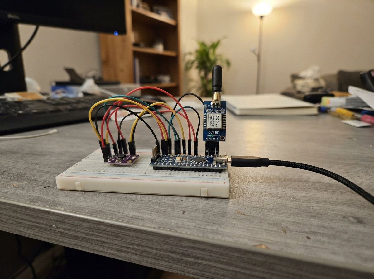
This guide walks through setting up a CC1101 Sub-GHz RF module alongside a BMP280 environmental sensor on an ESP32 microcontroller. The project demonstrates how to configure the CC1101 for wireless transmission while simultaneously reading temperature and pressure data from the BMP280 over I2C.
The guide includes a complete wiring diagram showing SPI connections for the CC1101 and I2C connections for the BMP280, a full parts list, and firmware with initialization routines, register configuration, and test transmission code. Follow the assembly steps to connect both modules, flash the firmware to the ESP32, and verify that both the radio and sensor are functioning correctly.
Wiring diagram

Gather all the parts
Assemble it in 5 steps
1. Turn the power off
Unplug the ESP32 USB cable before adding the BMP280 so a loose wire cannot touch the wrong pin while powered.
- Leave the existing CC1101 wires in their current positions.
- Do not connect either module to 5V — both modules use 3.3V logic and 5V can damage them.
2. Keep the CC1101 connections
Leave CC1101 VCC connected to 3V3 (power), GND to GND (ground), MOSI to GPIO32 (data), SCLK to GPIO33 (clock), MISO to GPIO19 (data), CSN to GPIO23 (radio select), and GDO0 to GPIO22 (signal).
- On the CC1101, SCLK is the same signal called SCK in the firmware.
- Do not connect the ANT pad to an ESP32 pin; it is only for a suitable 868 MHz antenna.
3. Connect BMP280 power
Connect the HW-611 BMP280 VCC pin to an ESP32 3V3 pin (power), then connect BMP280 GND to an ESP32 GND pin (ground). These can share the same 3V3 and GND rails already used by the CC1101.
- Read the labels printed beside the BMP280 pins rather than relying on their physical order.
- Make sure VCC and GND are not swapped — swapped power can damage the sensor.
4. Connect the BMP280 signal wires
Connect BMP280 SDA to ESP32 GPIO21 (data) and BMP280 SCL to ESP32 GPIO25 (clock). GPIO25 is used because GPIO22 is already connected to the CC1101 GDO0 signal.
- SDA and SCL are different wires; if the sensor is not found, check that they were not swapped.
- Do not connect BMP280 SCL to GPIO22 in this build — GPIO22 is already used by the CC1101.
5. Flash and check both modules
Plug the ESP32 back in over USB, press Deploy, then open Serial Monitor at 115200. It should print CC1101 OK and BMP280 OK, followed by temperature in C and pressure in hPa every two seconds.
- The BMP280 test tries both common sensor addresses automatically, so no address jumper change is needed.
- If BMP280 says NOT FOUND, unplug USB before changing wires.
Review all connections
1. Connections between "cc1101_1" and "ESP32"
2. Connections between "bmp280_1" and "ESP32"
Deploy the firmware
#include <Arduino.h>
#include <SPI.h>
#include <Wire.h>
#include <Adafruit_BMP280.h>


// Forward declarations
bool waitForMisoLow(uint32_t timeoutUs);
uint8_t ccStrobe(uint8_t command);
void ccWriteRegister(uint8_t address, uint8_t value);
uint8_t ccReadStatus(uint8_t address);
void ccWriteBurst(uint8_t address, const uint8_t *data, size_t length);
uint16_t wmbusCrc(const uint8_t *data, size_t length);
size_t encodeThreeOfSix(const uint8_t *input, size_t inputLength, uint8_t *output, size_t outputCapacity);
bool configureWmbusTTransmitter();
void sendWmbusTestTelegram();
void printBmpReading();

constexpr uint8_t LED_PIN = 2;
constexpr uint8_t CC1101_SCK = 33;
constexpr uint8_t CC1101_MISO = 19;
constexpr uint8_t CC1101_MOSI = 32;
constexpr uint8_t CC1101_CSN = 23;
constexpr uint8_t CC1101_GDO0 = 22;
constexpr uint8_t BMP280_SDA = 21;
constexpr uint8_t BMP280_SCL = 25;
constexpr uint8_t BMP280_I2C_ADDRESS = 0x76;

constexpr uint8_t SRES = 0x30;
constexpr uint8_t SIDLE = 0x36;
constexpr uint8_t SFTX = 0x3B;
constexpr uint8_t STX = 0x35;
constexpr uint8_t TXFIFO = 0x3F;
constexpr uint8_t PARTNUM = 0xF0;
constexpr uint8_t VERSION = 0xF1;
constexpr uint8_t MARCSTATE = 0xF5;
constexpr uint8_t TXBYTES = 0xFA;

Adafruit_BMP280 bmp;
bool bmpReady = false;
bool radioReady = false;
uint32_t lastTransmitMs = 0;
uint32_t sequenceNumber = 0;

bool waitForMisoLow(uint32_t timeoutUs = 2000) {
  const uint32_t started = micros();
  while (digitalRead(CC1101_MISO) != LOW) {
    if (micros() - started >= timeoutUs) return false;
  }
  return true;
}

uint8_t ccStrobe(uint8_t command) {
  digitalWrite(CC1101_CSN, LOW);
  waitForMisoLow();
  SPI.beginTransaction(SPISettings(4000000, MSBFIRST, SPI_MODE0));
  const uint8_t status = SPI.transfer(command);
  SPI.endTransaction();
  digitalWrite(CC1101_CSN, HIGH);
  return status;
}

void ccWriteRegister(uint8_t address, uint8_t value) {
  digitalWrite(CC1101_CSN, LOW);
  waitForMisoLow();
  SPI.beginTransaction(SPISettings(4000000, MSBFIRST, SPI_MODE0));
  SPI.transfer(address);
  SPI.transfer(value);
  SPI.endTransaction();
  digitalWrite(CC1101_CSN, HIGH);
}

uint8_t ccReadStatus(uint8_t address) {
  digitalWrite(CC1101_CSN, LOW);
  if (!waitForMisoLow()) {
    digitalWrite(CC1101_CSN, HIGH);
    return 0xFF;
  }
  SPI.beginTransaction(SPISettings(4000000, MSBFIRST, SPI_MODE0));
  SPI.transfer(address);
  const uint8_t value = SPI.transfer(0x00);
  SPI.endTransaction();
  digitalWrite(CC1101_CSN, HIGH);
  return value;
}

void ccWriteBurst(uint8_t address, const uint8_t *data, size_t length) {
  digitalWrite(CC1101_CSN, LOW);
  waitForMisoLow();
  SPI.beginTransaction(SPISettings(4000000, MSBFIRST, SPI_MODE0));
  SPI.transfer(address | 0x40);
  for (size_t i = 0; i < length; ++i) SPI.transfer(data[i]);
  SPI.endTransaction();
  digitalWrite(CC1101_CSN, HIGH);
}

uint16_t wmbusCrc(const uint8_t *data, size_t length) {
  uint16_t crc = 0x0000;
  for (size_t i = 0; i < length; ++i) {
    crc ^= static_cast<uint16_t>(data[i]) << 8;
    for (uint8_t bit = 0; bit < 8; ++bit) {
      crc = (crc & 0x8000) ? static_cast<uint16_t>((crc << 1) ^ 0x3D65) : static_cast<uint16_t>(crc << 1);
    }
  }
  return static_cast<uint16_t>(~crc);
}

// EN 13757-4 T-mode: each high nibble, then low nibble, becomes a six-bit 3-of-6 symbol.
const uint8_t THREE_OF_SIX[16] = {
  0x16, 0x0D, 0x0E, 0x0B, 0x1C, 0x19, 0x1A, 0x13,
  0x2C, 0x25, 0x26, 0x23, 0x34, 0x31, 0x32, 0x29
};

size_t encodeThreeOfSix(const uint8_t *input, size_t inputLength, uint8_t *output, size_t outputCapacity) {
  uint32_t bits = 0;
  uint8_t bitCount = 0;
  size_t out = 0;
  for (size_t i = 0; i < inputLength; ++i) {
    // EN 13757-4 T1 sends the high nibble first, then the low nibble.
    // For 0x0A this begins 0x5A 0x67, which is the scanner's expected 3-of-6 prefix.
    const uint8_t nibbles[] = {static_cast<uint8_t>(input[i] >> 4), static_cast<uint8_t>(input[i] & 0x0F)};
    for (uint8_t nibble : nibbles) {
      bits = (bits << 6) | THREE_OF_SIX[nibble];
      bitCount += 6;
      while (bitCount >= 8) {
        if (out >= outputCapacity) return 0;
        bitCount -= 8;
        output[out++] = static_cast<uint8_t>(bits >> bitCount);
      }
    }
  }
  if (bitCount > 0) {
    if (out >= outputCapacity) return 0;
    output[out++] = static_cast<uint8_t>(bits << (8 - bitCount));
  }
  return out;
}

bool configureWmbusTTransmitter() {
  ccStrobe(SRES);
  delay(2);
  const uint8_t part = ccReadStatus(PARTNUM);
  const uint8_t version = ccReadStatus(VERSION);
  if (part != 0x00 || (version != 0x04 && version != 0x14)) return false;

  // TI AN067 Radio Link B: 868.95 MHz, 100 kchip/s MSK, sync word 0x543D.
  const struct { uint8_t reg; uint8_t value; } settings[] = {
    {0x00, 0x06}, {0x01, 0x2E}, {0x02, 0x02}, {0x03, 0x07},
    {0x04, 0x54}, {0x05, 0x3D}, {0x06, 0xFF}, {0x07, 0x04},
    {0x08, 0x00}, {0x09, 0x00}, {0x0A, 0x00}, {0x0B, 0x08},
    {0x0C, 0x00}, {0x0D, 0x21}, {0x0E, 0x6B}, {0x0F, 0xD0},
    {0x10, 0x5B}, {0x11, 0xF8}, {0x12, 0x05}, {0x13, 0x22},
    {0x14, 0xF8}, {0x15, 0x50}, {0x16, 0x07}, {0x17, 0x00},
    {0x18, 0x18}, {0x19, 0x2E}, {0x1A, 0xBF}, {0x1B, 0x43},
    {0x1C, 0x09}, {0x1D, 0xB5}, {0x21, 0xB6}, {0x22, 0x10},
    {0x23, 0xEA}, {0x24, 0x2A}, {0x25, 0x00}, {0x26, 0x1F},
    {0x2C, 0x81}, {0x2D, 0x35}, {0x2E, 0x09}
  };
  for (const auto &setting : settings) ccWriteRegister(setting.reg, setting.value);
  ccStrobe(SIDLE);
  ccStrobe(SFTX);
  return true;
}

void sendWmbusTestTelegram() {
  // Complete unencrypted format-A T1 telegram. It includes CI=0x7A, its
  // four-byte short transport header, and one temperature record (DIF=0x02,
  // VIF=0x6D: signed temperature in 0.01 C units). This is a test ID only.
  const int16_t temperatureCentiC = bmpReady
      ? static_cast<int16_t>(bmp.readTemperature() * 100.0F)
      : 0;
  uint8_t frame[] = {
    // L=18 bytes after L, excluding the two CRC bytes for each physical block.
    0x12, 0x44, 0x2F, 0x2F, 0x12, 0x34, 0x56, 0x78, 0x01, 0x07,
    0x7A, static_cast<uint8_t>(sequenceNumber), 0x00, 0x00, 0x00, 0x02,
    0x00, 0x00, 0x00, 0x00, 0x00, 0x00, 0x00
  };
  // Format A has a CRC after each 16-byte data block. The first block includes
  // L through DIF; the second contains VIF and the two-byte temperature value.
  const uint16_t crc1 = wmbusCrc(frame, 16);
  frame[16] = static_cast<uint8_t>(crc1 & 0xFF);
  frame[17] = static_cast<uint8_t>(crc1 >> 8);
  frame[18] = 0x6D;
  frame[19] = static_cast<uint8_t>(temperatureCentiC & 0xFF);
  frame[20] = static_cast<uint8_t>((static_cast<uint16_t>(temperatureCentiC) >> 8) & 0xFF);
  const uint16_t crc2 = wmbusCrc(&frame[18], 3);
  frame[21] = static_cast<uint8_t>(crc2 & 0xFF);
  frame[22] = static_cast<uint8_t>(crc2 >> 8);

  // 23 raw bytes expand to 35 bytes with 3-of-6 coding; leave one byte spare.
  uint8_t encoded[36];
  const size_t encodedLength = encodeThreeOfSix(frame, sizeof(frame), encoded, sizeof(encoded));
  if (encodedLength == 0 || encodedLength > 64) {
    Serial.println("wM-Bus encoding failed.");
    return;
  }

  // Fixed-length packet mode: tell CC1101 exactly how many encoded bytes
  // are in this telegram. A length of 255 with only 20 queued bytes causes
  // a TX FIFO underflow before the radio can finish the packet.
  ccWriteRegister(0x06, static_cast<uint8_t>(encodedLength));
  ccStrobe(SIDLE);
  ccStrobe(SFTX);
  ccWriteBurst(TXFIFO, encoded, encodedLength);
  ccStrobe(STX);

  // The FIFO must drain and MARCSTATE must return to IDLE.
  const uint32_t txStarted = millis();
  uint8_t marcState = ccReadStatus(MARCSTATE);
  while (marcState != 0x01 && millis() - txStarted < 100U) {
    delay(1);
    marcState = ccReadStatus(MARCSTATE);
  }
  const uint8_t txBytes = ccReadStatus(TXBYTES);
  const bool txUnderflow = (txBytes & 0x80U) != 0;
  const uint8_t queuedBytes = txBytes & 0x7FU;
  Serial.printf("CC1101 TX | encoded=%u | MARCSTATE=0x%02X | FIFO=%u | underflow=%s\n",
                static_cast<unsigned>(encodedLength), marcState, queuedBytes, txUnderflow ? "YES" : "no");
  ccStrobe(SIDLE);
  ccStrobe(SFTX);

  digitalWrite(LED_PIN, HIGH);
  delay(30);
  digitalWrite(LED_PIN, LOW);
  Serial.printf("WMBUS TX #%lu | 868.95 MHz | T-mode | frame:", static_cast<unsigned long>(sequenceNumber));
  for (uint8_t byte : frame) Serial.printf(" %02X", byte);
  Serial.println();
}

void printBmpReading() {
  if (bmpReady) {
    Serial.printf("BMP280 | %.2f C | %.2f hPa\n", bmp.readTemperature(), bmp.readPressure() / 100.0F);
  }
}

void setup() {
  Serial.begin(115200);
  delay(400);
  pinMode(LED_PIN, OUTPUT);
  pinMode(CC1101_CSN, OUTPUT);
  pinMode(CC1101_MISO, INPUT);
  digitalWrite(LED_PIN, LOW);
  digitalWrite(CC1101_CSN, HIGH);
  SPI.begin(CC1101_SCK, CC1101_MISO, CC1101_MOSI, CC1101_CSN);
  Wire.begin(BMP280_SDA, BMP280_SCL);

  Serial.println("\nESP32 wM-Bus T-mode test transmitter");
  bmpReady = bmp.begin(BMP280_I2C_ADDRESS);
  Serial.println(bmpReady ? "BMP280 OK at 0x76." : "BMP280 not found; transmission will continue.");
  radioReady = configureWmbusTTransmitter();
  if (!radioReady) {
    Serial.println("CC1101 was not detected. Check SPI wiring.");
    return;
  }
  Serial.println("CC1101 OK. A reserved test telegram is sent once every 3 seconds.");
  sendWmbusTestTelegram();
  lastTransmitMs = millis();
}

void loop() {
  if (!radioReady) return;
  const uint32_t now = millis();
  if (now - lastTransmitMs >= 3000UL) {
    ++sequenceNumber;
    printBmpReading();
    sendWmbusTestTelegram();
    lastTransmitMs = now;
  }
}
Remix this project
Make it yours in one click
Open a full copy of this project in your own Schematik workspace — diagram, code, parts, and assembly steps included. Swap the sensor, add features, or redesign the whole thing with AI. The author's original stays untouched.